Energy-saving type parallel connection vacuum generator
A vacuum generator, energy-saving technology, applied in the direction of machine/engine, non-displacement pump, mechanical equipment, etc., can solve the problem of inability to solve the contradiction between fast production and energy saving, reduce the weight of the whole machine and meet the speed of response , the effect of saving energy
- Summary
- Abstract
- Description
- Claims
- Application Information
AI Technical Summary
Problems solved by technology
Method used
Image
Examples
Embodiment 1
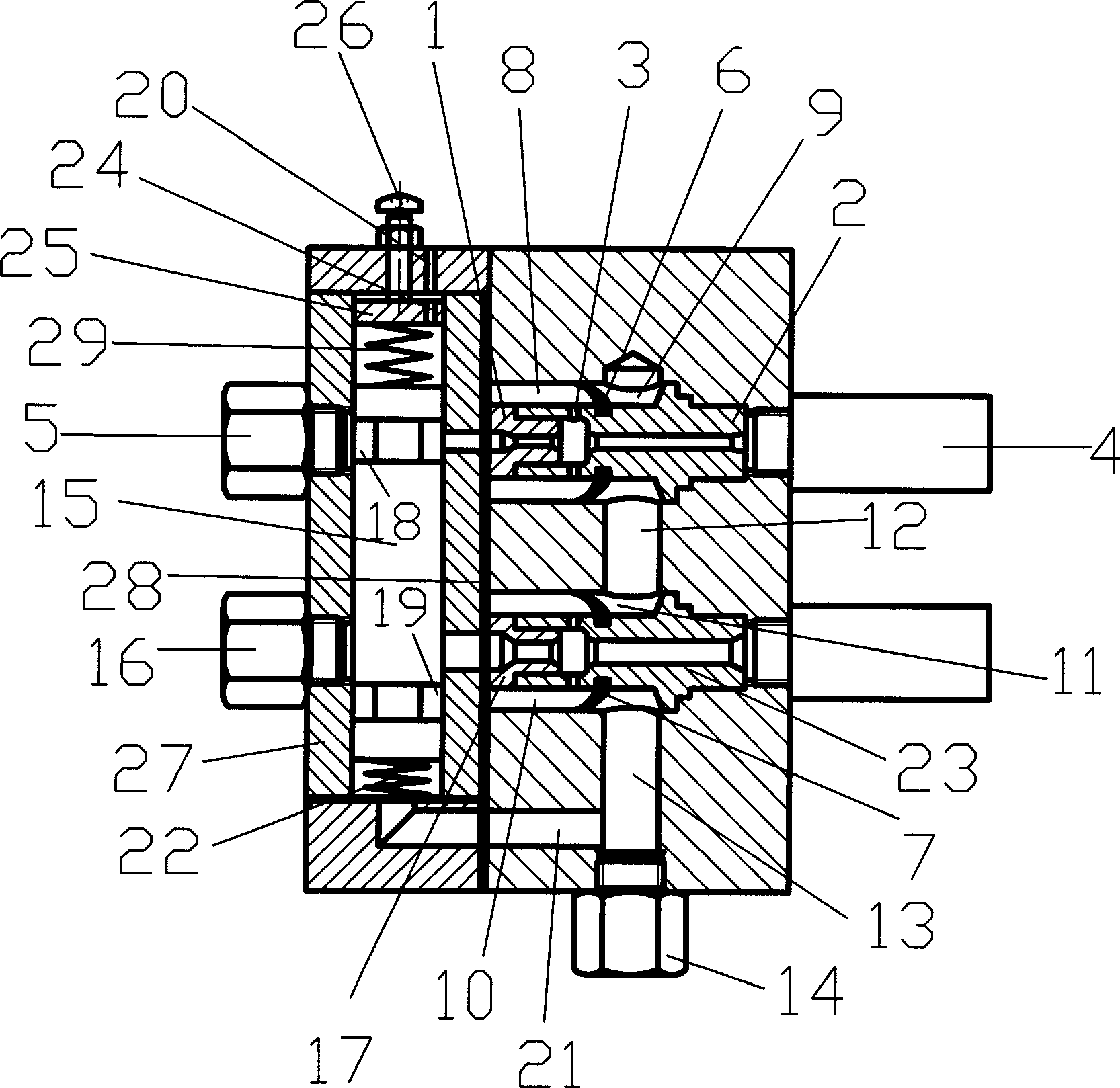
[0017] Energy-saving parallel vacuum generator, which includes parallel first vacuum generator assembly and second vacuum generator assembly, each vacuum generator assembly includes compressed gas connection, nozzle, expansion tube, vacuum chamber and muffler , taking the first vacuum generator assembly as an example: there is a first nozzle 1 and a first expansion tube 2 in the cavity of the machine body, the first nozzle 1 and the first expansion tube 2 are in sealing connection, the first nozzle 1 The pipeline of the pipeline and the first expansion tube 2 constitutes the first air flow channel, the first nozzle 1, the first expansion tube 2 and the inner wall of the body enclose the first vacuum chamber, and the first air flow channel passes through the first suction hole 3 and the The first vacuum chamber is connected, the end of the first expansion tube 2 is connected to the first muffler 4, the first compressed gas joint 5, the first nozzle 1, the first expansion tube 2 ...
Embodiment 2
[0024] refer to figure 1A backing plate 25 with a longitudinal through hole 24 is fixedly connected in the valve chamber, the backing plate 25 is connected with the adjusting screw 26, and the backing plate 25 is located between the valve lower cover plate and the valve core 15 , the adjusting screw 26 extends out of the valve body, and the backing plate is connected with the valve core through an adjusting spring 29 . The preload of the spring can be adjusted by adjusting the adjusting screw 26 . The rest of the structure and implementation are the same as in Embodiment 1.
Embodiment 3
[0026] refer to figure 1 , there is a sealing ring 28 between the valve body and the body. After the sealing ring 28 is set, it can be ensured that the vacuum generator can work normally. The rest of the structure and implementation are the same as in Embodiment 1.
PUM
 Abstract
Description
Claims
Application Information
 - R&D
- Intellectual Property
- Life Sciences
- Materials
- Tech Scout
- Unparalleled Data Quality
- Higher Quality Content
- 60% Fewer Hallucinations
Browse by: Latest US Patents, China's latest patents, Technical Efficacy Thesaurus, Application Domain, Technology Topic, Popular Technical Reports.
© 2025 PatSnap. All rights reserved.Legal|Privacy policy|Modern Slavery Act Transparency Statement|Sitemap|About US| Contact US: help@patsnap.com

