Combine

A technology for combine harvesters and engines, which is used in harvesters, cutters, steering mechanisms, etc., can solve the problems of not increasing the speed, simplifying the driving structure, and easily generating shocks, so as to prevent the reduction of the driving speed and reduce the blockage. , the effect of simplification reduction

Inactive Publication Date: 2005-09-14
YANMAR CO LTD
View PDF0 Cites 12 Cited by
  • Summary
  • Abstract
  • Description
  • Claims
  • Application Information

AI Technical Summary

Problems solved by technology

[0002] In the past, for example, as shown in Japanese Unexamined Publication No. 62-163826, in a combine harvester or the like that is provided with left and right travel crawler belts, since the speed change output of the hydraulic pump of the hydraulic transmission mechanism is used to drive the travel part (travel Crawler), at the same time, directly connects the input side and the output side of the hydraulic transmission mechanism at the highest speed through the constant speed mechanism, so there is a problem of poor operation due to the output of the highest speed of the hydraulic transmission mechanism with a large horsepower lost due to instability. , and at the same time, even if the output from the hydraulic transmission mechanism is converted to the output of the constant speed mechanism, the speed will not increase, and there are problems such as difficulty in easily improving the operational performance.
In addition, because of the front and rear rotation difference (speed difference) directly connected by the constant speed mechanism, while there are problems such as easy shocks, when the traveling part is driven by the constant speed output of the constant speed mechanism, for example, in hydraulic transmission In the hydraulic transmission mechanism with non-uniform characteristics, there are problems that it is difficult to make the discharge volumes of the hydraulic pump and the motor equal, or it is impossible to effectively recover the lost horsepower, or to increase the load. Problems such as simplification of the driving structure of the working unit and reduction of transmission loss

Method used


Image

  • Combine
  • Combine
  • Combine

Examples


Embodiment Construction

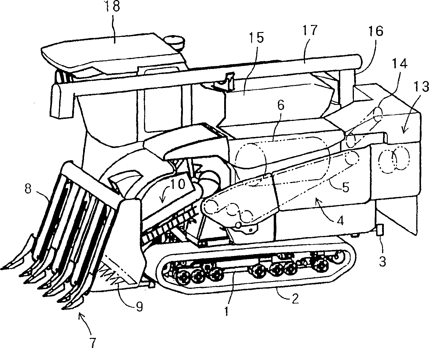
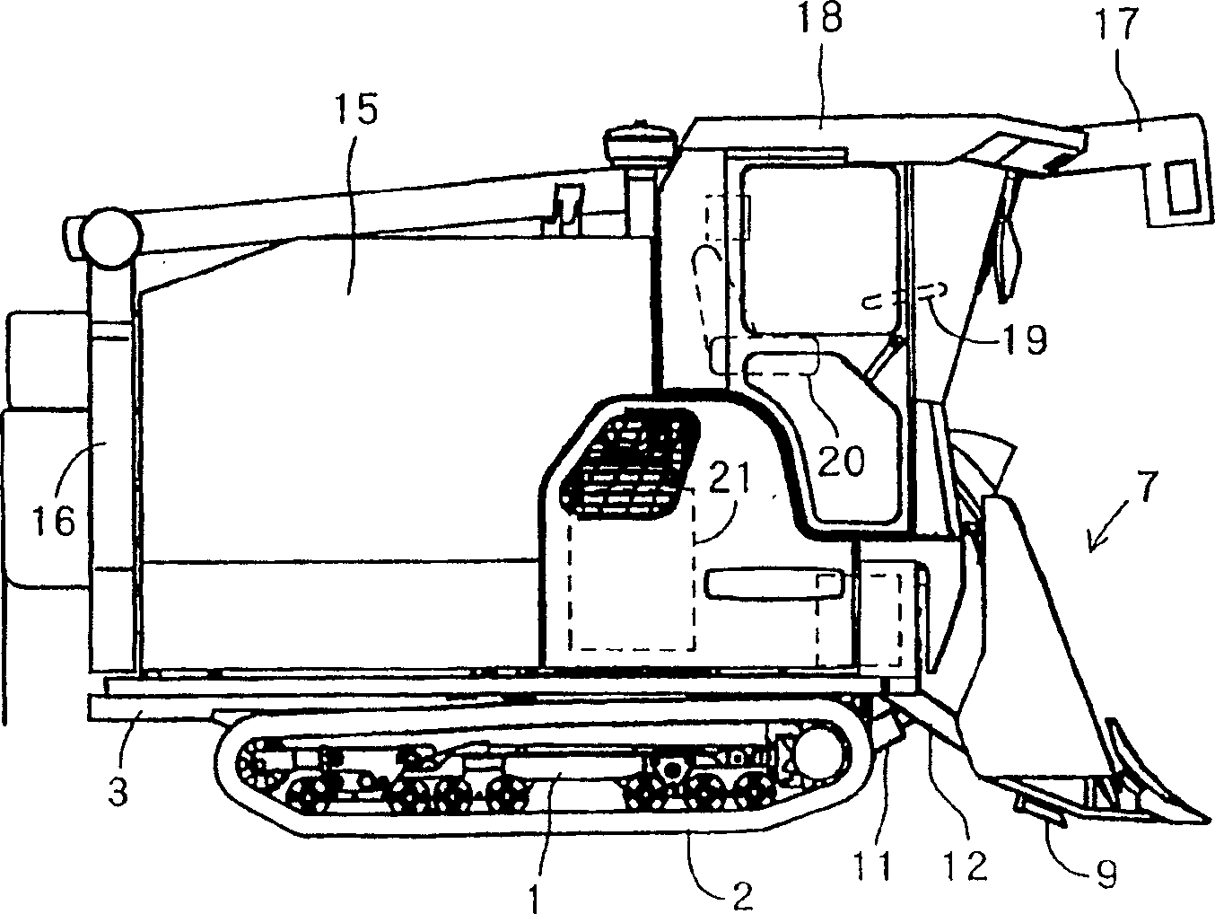
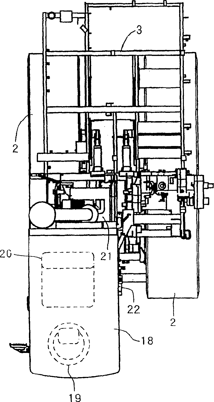
[0047] Embodiments of the present invention will be described in detail below with reference to the accompanying drawings. figure 1 It is a perspective view of the whole combine harvester, figure 2 is the same as the right side view, image 3 It is an explanatory top view, in which 1 is a pair of left and right bogie frames on which a pair of left and right traveling crawler belts 2 are installed, 3 is a machine platform erected on the above-mentioned left and right bogie frames 1, and 4 is a set of feed chains 5 on On the left side, the threshing part of the threshing machine that has built-in operation tube 6 and processing tube, 7 is to have the harvesting part of raising mechanism 8 and harvesting knife 9 and grain stalk conveying mechanism 10 etc., and 11 is to pass through harvesting frame 12, make The hydraulic lifting cylinder of the harvesting section 7 lifting, 13 is the straw discharge processing section facing the 14 terminals of the straw discharge chain, the 15...


PUM


Abstract

A combine for driving a traveling section (2) by transmitting the power of an engine (21) to a transmission case (22) provided with a traveling speed change mechanism (40), characterized in that the power of the engine (21) is transmitted to a counter case (25) in order to drive a threshing section (4) by a substantially constant rotational output and the speed change output from the traveling speed change mechanism (40) is transmitted to the counter case (25) in order to drive a reaping section (7) at a speed synchronous with the vehicle speed, and the counter case (25) is arranged such that the reaping section (7) is driven at a substantially constant speed by a substantially constant rotational output from the counter case (25). The counter case (25) for driving the threshing section (4) at a constant speed can also drive the reaping section (7) at a speed synchronous with the vehicle speed or at a substantially constant speed, and the reaping section (7) can be driven at a constant speed utilizing a part of the driving system of the threshing section (4), resulting in simplification of driving structure of the reaping section (7), or the like and reduction of transmission loss.

Description

technical field [0001] This invention relates to the combine harvester which attaches and installs a pair of right and left running crawler belts, and moves, for example. technical background [0002] In the past, for example, as shown in Japanese Unexamined Publication No. 62-163826, in a combine harvester or the like that is provided with left and right travel crawler belts, since the speed change output of the hydraulic pump of the hydraulic transmission mechanism is used to drive the travel part (travel Crawler), at the same time, directly connects the input side and the output side of the hydraulic transmission mechanism at the highest speed through the constant speed mechanism, so there is a problem of poor operation due to the output of the highest speed of the hydraulic transmission mechanism with a large horsepower lost due to instability. , At the same time, even if the output from the hydraulic transmission mechanism is converted into the output of the constant sp...

Claims


Application Information

Patent Timeline
Patent Type & Authority Applications(China)
IPC IPC(8): A01D69/00A01D41/127A01D69/03B60K17/10B62D11/08B62D11/18F16H47/02
CPCA01D41/1274A01D69/00
Inventor 日高茂实
Owner YANMAR CO LTD
Why Eureka
Try Eureka