Minisize low speed airspeedometer for mini aircrafts

A technology of micro-aircraft and airspeed meter, which is applied in the direction of measuring fluid velocity by using differential pressure, which can solve the problems of large volume, complex structure, large volume and weight of pitot sensor

Inactive Publication Date: 2005-09-21
TSINGHUA UNIV
View PDF0 Cites 21 Cited by
  • Summary
  • Abstract
  • Description
  • Claims
  • Application Information

AI Technical Summary

Problems solved by technology

[0005] 1. The pitot tube has a large volume and weight, so it must be miniaturized;
[0006] 2. The traditional differential pressure sensor has a large volume a

Method used


Image

  • Minisize low speed airspeedometer for mini aircrafts
  • Minisize low speed airspeedometer for mini aircrafts
  • Minisize low speed airspeedometer for mini aircrafts

Examples


Embodiment Construction

[0036] Further describe the present invention below in conjunction with accompanying drawing and embodiment:

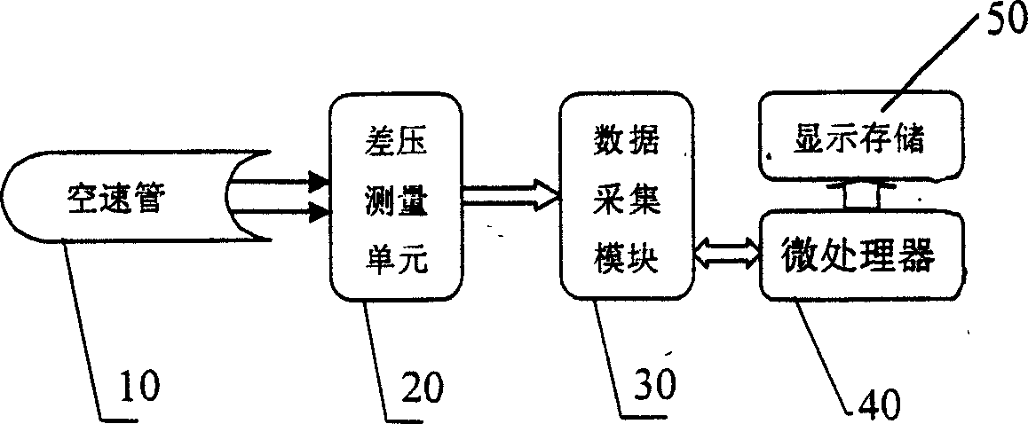
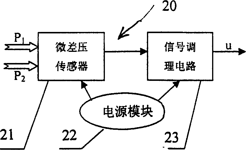
[0037] See attached figure 1 , the miniature low-speed airspeed meter of the present invention is designed based on the principle of differential pressure measurement, and mainly includes a micropitotometer unit 10, a micro-differential pressure measurement unit 20, a data acquisition module 30, a processor 40, and a display storage unit 50; Its working principle is briefly described as follows:

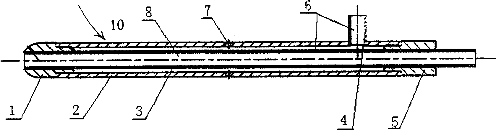
[0038] Install the micro pitot unit 10 at a proper position in the flow field to be measured, facing the incoming flow direction. The mini pitot 10 outputs the total pressure P at the same time 1 and static pressure P 2 , and the airspeed near the measurement point in the flow field is denoted as V A , the gas density in the flow field is ρ, and q represents P 1 with P 2 pressure difference, there is q = ρ 2 ...


PUM


Abstract

This invention relates to micro aviator low speed air speedometer, which comprises orderly micro air speedometer, micro voltage difference measurement unit, data collection module, microprocessor and display and memory unit, wherein, the air speedometer has the micro design comprising tube head, outer tube, bus voltage tube and static tube. The outer tube is located with static hole and the bus voltage tube is inserted with tube head and the other end of the outer tube is sealed. The bus and static voltage are separately conducted by bus tube and static tube. The data collection module is connected to the output end of signal adjusting circuit of micro voltage difference. The data collection module is A/D converter circuit module to convert the received signals put to the microprocessor, wherein the microprocessor is connected to the display memory unit.

Description

technical field [0001] The invention relates to a low-airspeed measuring device, in particular to a small-volume, light-weight and high-reliability miniature low-speed airspeed gauge for micro-aircraft. Background technique [0002] The measurement of airspeed plays a very important role in the safe flight and automatic control of the aircraft. The design principles of traditional airspeed meters mainly include hot wire type, differential pressure type, and rotary wheel type. The sensitive element of the hot wire airspeed meter is the thermistor wire (sheet), and the current flows through the thermistor wire (sheet), causing the resistor to heat up; when the gas flows around the resistor, it will take away a certain amount of heat; Under the current, the temperature of the resistance wire (sheet) has a certain functional relationship with the flow rate of the gas, and the current wind speed can be obtained by measuring the voltage at both ends of the resistance. The rotary...

Claims


Application Information

Patent Timeline
IPC IPC(8): G01P5/14
Inventor 熊沈蜀周兆英王晓浩王立代祝志晨
Owner TSINGHUA UNIV
Why Eureka
Try Eureka