

Driving device
A technology of driving device and driving shaft, which is applied in the direction of electromechanical devices, electric components, transportation and packaging, etc., can solve the problems of cost increase, achieve the effect of reducing cogging effect and excellent assembly work
- Summary
- Abstract
- Description
- Claims
- Application Information
AI Technical Summary
Problems solved by technology
Method used
Image

Examples
Embodiment 1
[0037] Hereinafter, embodiments of the present invention will be described with reference to the drawings.
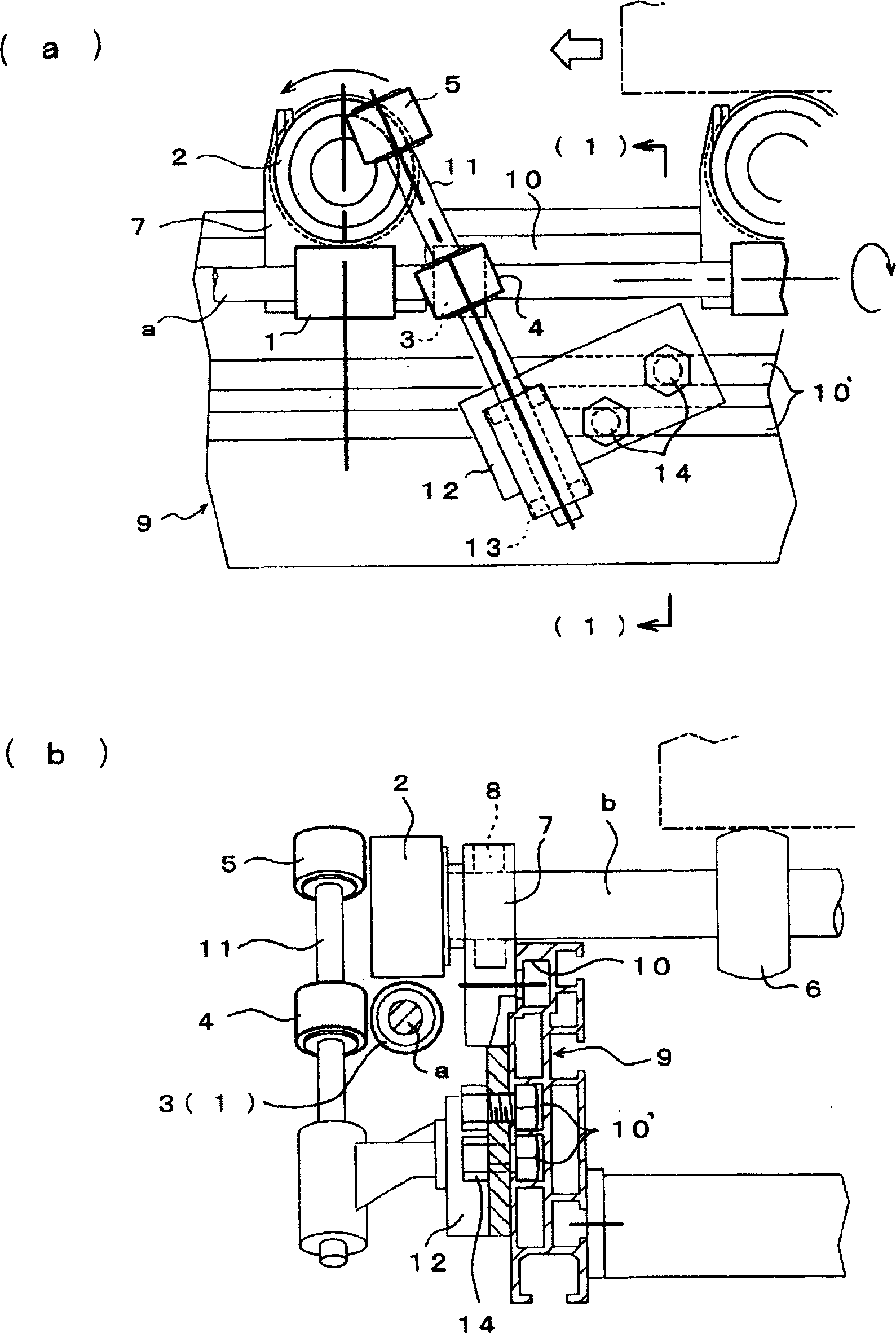
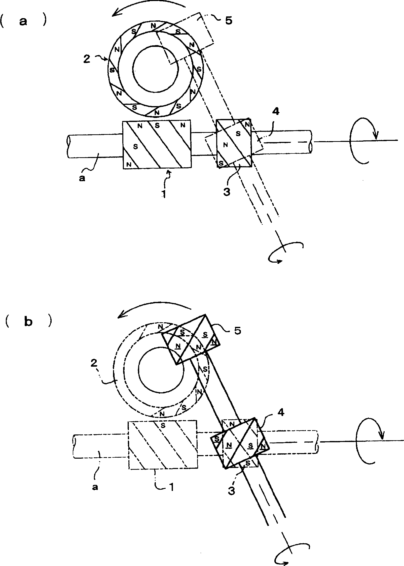
[0038] figure 1 and figure 2 It shows the driving device that transmits power to the driven magnetic wheel by 2 systems (main transmission system + first auxiliary transmission system). In the figure, symbol 1 represents the driving magnetic wheel, 2 represents the driven magnetic wheel, and 3 represents the auxiliary driving magnetic wheel , 4 represents the first secondary driven magnetic wheel, 5 represents the second secondary driven magnetic wheel, the main transmission system is composed of the driving magnetic wheel 1 and the driven magnetic wheel 2, the first secondary transmission system is composed of the secondary driving magnetic wheel 3 and the The first secondary driven magnetic wheel 4 , the second secondary driven magnetic wheel 5 and the driven magnetic wheel 2 are formed.
[0039] The above-mentioned drive magnet wheel 1 is formed by a short cylindr...
Embodiment 2
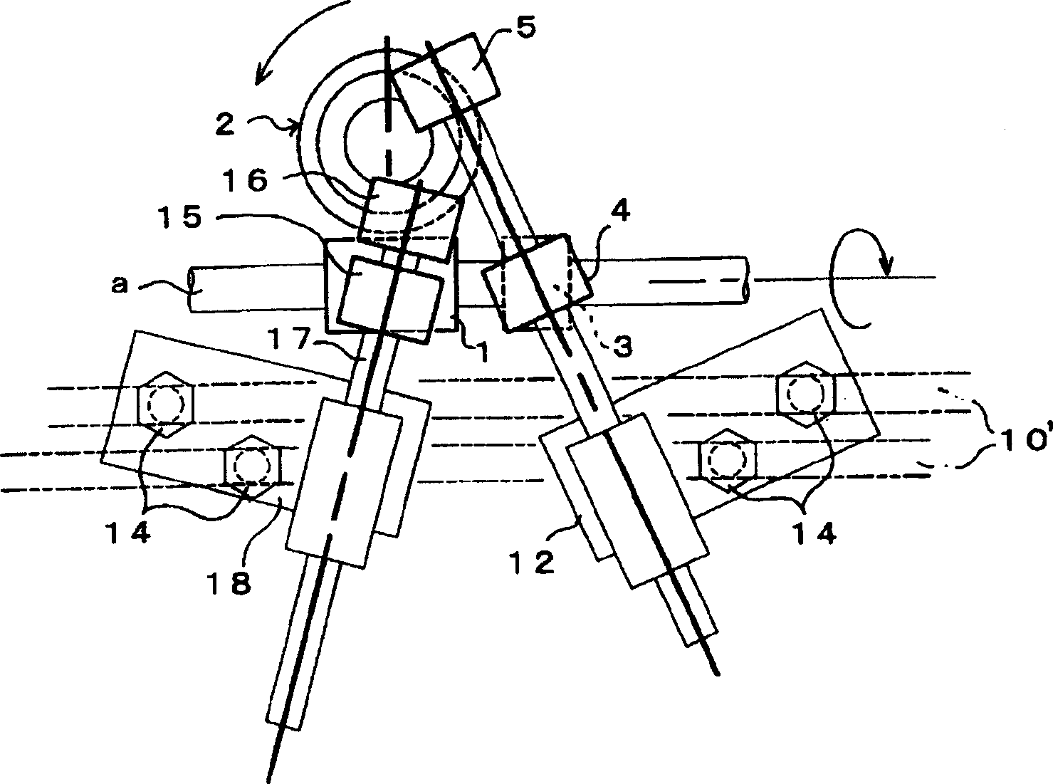
[0049] image 3 It shows that in the structure of the aforementioned embodiment 1, a driving device of a second auxiliary transmission system is added, and the added second auxiliary transmission system utilizes the driving magnetic wheel 1 to transmit power from the axial end surface of the driven magnetic wheel 2 . Components that are the same as those in Embodiment 1 are denoted by the same symbols and their descriptions are omitted.
[0050] The added 2nd sub-transmission system is the same as the 1st sub-driven magnetic wheel 4 and the 2nd sub-driven magnetic wheel 5 that constitute the sub-transmission system in Embodiment 1, and possesses: a 3rd sub-driven magnetic wheel corresponding to the drive magnetic wheel 1. The driven magnet wheel 15, the 4th sub driven magnet wheel 16 corresponding to the axial end face of the driven magnet wheel 2, and the 3rd sub driven magnet wheel 15 and the 4th sub driven magnet wheel 16 are supported on the same platform. The fulcrum 17 ...
Embodiment 3
[0054] In Embodiment 1 and Embodiment 2 above, the power transmission to the driven magnet wheel by means of the auxiliary transmission system utilizes the axial end face of the driven magnet wheel, but the outer peripheral surface of the driven magnet wheel may also be used to form the auxiliary transmission system. The relevant structures are described below. The structure of the main transmission system from the driving magnetic wheel to the driven magnetic wheel and the sub-transmission system are the same as those of the first and second embodiments, and the same structural parts are denoted by the same symbols, and their descriptions are omitted.
[0055] Figure 5 Shown is a driving device configured on one side with a sub-transmission system that transmits power to the driven magnetic wheel; it is configured such that the rotation of the sub-driven magnetic wheel 3 fixed to the drive shaft a passes through two intermediate driven magnetic wheels 19, 20 is transmitted ...
PUM
 Abstract
Description
Claims
Application Information