
Sewing machine

A sewing machine and fan impeller technology, which is applied to sewing machine components, sewing equipment, sewing machine control devices, etc., can solve the problems of not being able to make full use of motor efficiency, stop the motor in advance, etc., and achieve effective guidance and easy installation

Inactive Publication Date: 2012-03-28
DURKOPP ADLER AG
View PDF0 Cites 0 Cited by
  • Summary
  • Abstract
  • Description
  • Claims
  • Application Information

AI Technical Summary

Problems solved by technology

In said known sewing machines there are problems with the cooling of the motor mounted in the top arm which, for example, can cause an early stop of the motor or an inability to fully utilize the efficiency of the motor

Method used


Image

  • Sewing machine
  • Sewing machine
  • Sewing machine

Examples


Embodiment Construction

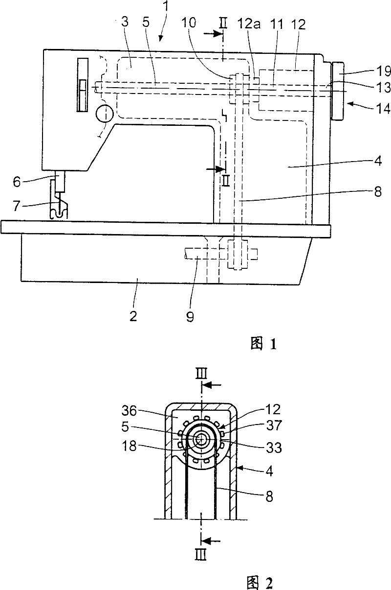
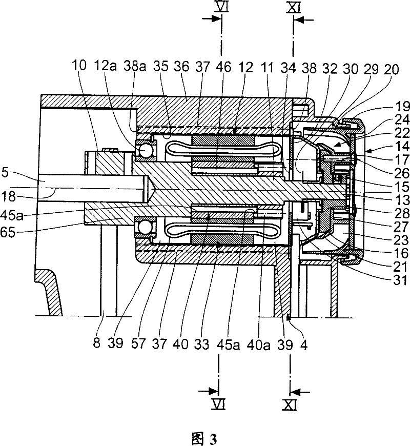
[0025] Figures 1 to 13 The sewing machine 1 shown in the figure comprises a base plate 2 in the form of a housing, a top arm 3 and a column 4 connecting the two parts. That is, the overall shape of the sewing machine 1 is roughly C-shaped. An arm shaft 5 is supported in the top arm 3, through which a needle bar 6 with a needle 7 is driven to reciprocate up and down by means of a crank driver (not shown). The arm shaft 5 drives via a (belt) belt drive 8 and a shaft 9 mounted in the base plate 2 a thread hook, also not shown, which is mounted in the base plate 2 and assigned to the needle 7 .

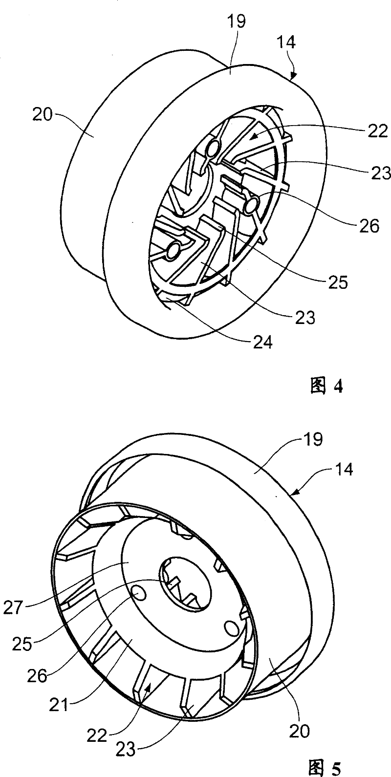
[0026] A flange portion 10 is provided on the arm shaft 5 at the level of the belt drive 8 . The arm shaft 5 is relatively non-rotatably coupled via a flange portion 10 to a drive shaft 11 of an arm shaft drive motor 12 aligned with the arm shaft. The drive shaft 11 is supported by an axial / radial bearing 12a at a position adjacent to the flange portion 10 . A hand wheel 14 is sleeve...


PUM


Abstract

The present invention relates to a a sewing machine (1), which includes: a substrate (2); a top arm (3) in which a follower arm axis (5) is supported; and a column (4) connecting the said substrate and the top arm (3). A handwheel (14), is connected to the said arm axis (5) which is not capable of relative rotating each other, and is disposed coaxially with the said arm axis (5), and manually operates the said arm axis (5). The driving device of the said arm axis (5) is formed by a motor (12) installed in the top arm (3), and the driving axis of the said motor aligns to the said arm axis (5).The said handwheel (14) has a fan impeller (22) for cooling the said motor. This enables the effective cooling of the motor.

Description

technical field [0001] The invention relates to a sewing machine, which comprises: a base plate; a top arm supporting a driven arm shaft inside; a column connecting the base plate and the top arm; a non-rotatable connection with the arm shaft and the A hand wheel arranged coaxially with the arm shaft for manually operating the arm shaft, wherein a motor mounted in the top arm forms the drive of the arm shaft, the motor's The drive shaft is aligned with the arm axis. Background technique [0002] Such sewing machines are known from the published prior use. In said known sewing machines there are problems with the cooling of the motor mounted in the top arm, which can for example cause an early stop of the motor or an inability to fully utilize the efficiency of the motor. Contents of the invention [0003] It is therefore the object of the invention to improve a sewing machine of the type mentioned at the outset in such a way that effective cooling of the motor installed ...

Claims


Application Information

Patent Timeline
Patent Type & Authority Patents(China)
IPC IPC(8): D05B69/30D05B71/00H02K5/20
Inventor S·霍沙加西H·弗兰辛
Owner DURKOPP ADLER AG
Learn More