Drill stem oil pipe or sucker rod marking method
A marking method and sucker rod technology, which is applied in the direction of drill pipe, drill pipe, casing, etc., can solve the problems of high cost of marking oil pipes, high cost of oil fields, huge consumption, etc., and achieve long-term reliable use of marking, Scientifically optimize the combination and withstand the effect of high-speed erosion and corrosion
- Summary
- Abstract
- Description
- Claims
- Application Information
AI Technical Summary
Problems solved by technology
Method used
Image
Examples
Embodiment 1
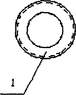
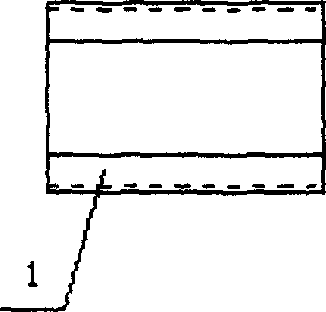
[0021] In this embodiment, the oil pipe with an outer diameter of 73 mm is taken as an example. The size of the coupling 2 is: the inner diameter is 73 mm, and the gap width connected in the oil pipe is 25.4 mm. It is an API oil pipe buckle, 10 buckles / inch, and the taper is 1:16; figure 1 , 2 , 3, the present embodiment establishes the annular structure carrier 1, carries the coding content of product information, then puts the identification ring tool into the middle part of the coupling 2 of the oil pipe 3 (or pipe rod), and the annular structure carrier 1 and the The connection between the collars 2 is threaded, and there is a gap between the ring structure carrier 1 and the pipe rod 3; the outer diameter of the ring structure carrier 1 is 73mm, the length is 23mm, the wall thickness is 5.0mm, and the outer diameter is threaded. , the coupling 2 buckle of the tubing 3 is: 10 buckles / inch;
[0022] The annular structure is made of metal materials such as oil pipe steel or ...
Embodiment 2
[0027] The difference from the embodiment is: taking the drill pipe as an example, the size of the coupling 2 is: the inner diameter is 150.0mm, and the gap width between the drill pipes in the coupling 2 is 12.5mm, which is an API drill pipe buckle. In this embodiment, the ring Shaped structure carrier 1 (the present embodiment is engineering plastics such as nylon material), carries the coding content of product information, then puts the logo ring tool into the middle part of the collar 2 of the drill pipe, the ring structure carrier 1 and the drill pipe 3 There is an interval between them; the outer diameter of the annular structure carrier 1 is 150.0mm, the length is 10.0mm, and the wall thickness is 10.0mm.
Embodiment 3
[0029] The difference from the embodiment is that: taking the 25.4 sucker rod as an example, the size of the coupling 2 is: the inner diameter is 34.9mm, and the gap width between the sucker rods in the coupling 2 is 10.0mm, which is an API sucker rod buckle. The embodiment establishes a ring-shaped structure carrier 1 (this embodiment is engineering plastics such as polyester resin), which carries the coded content of product information, and then puts the identification ring into the middle part of the coupling 2 of the sucker rod with a tool, and the ring-shaped structure There is a space between the carrier 1 and the pipe rod 3; the ring-shaped carrier 1 has an outer diameter of 34.9 mm, a length of 10.0 mm, and a wall thickness of 5.0 mm.
PUM
 Abstract
Description
Claims
Application Information
 - R&D
- Intellectual Property
- Life Sciences
- Materials
- Tech Scout
- Unparalleled Data Quality
- Higher Quality Content
- 60% Fewer Hallucinations
Browse by: Latest US Patents, China's latest patents, Technical Efficacy Thesaurus, Application Domain, Technology Topic, Popular Technical Reports.
© 2025 PatSnap. All rights reserved.Legal|Privacy policy|Modern Slavery Act Transparency Statement|Sitemap|About US| Contact US: help@patsnap.com


