Forced heat exchange tube

A technology that enhances heat exchange and heat exchange tubes. It is applied to tubular elements, heat exchange equipment, lighting and heating equipment, etc. It can solve the problems of heat transfer performance degradation, poor synergy between speed and temperature gradient, etc., and achieve increased heat transfer. Heat area, effect of improving heat transfer coefficient

Inactive Publication Date: 2005-10-05
XI AN JIAOTONG UNIV
View PDF2 Cites 25 Cited by
  • Summary
  • Abstract
  • Description
  • Claims
  • Application Information

AI Technical Summary

Problems solved by technology

However, in the currently used light pipes, due to the direction of fluid flow, the boundary layer formed by the fluid on the surface of the fin will gradually thicken, making the coordination of velocity and temperature gradient worse, which will reduce the heat transfer performance.

Method used


Image

  • Forced heat exchange tube
  • Forced heat exchange tube
  • Forced heat exchange tube

Examples


Embodiment Construction

[0011] The present invention will be described in further detail below in conjunction with the accompanying drawings.

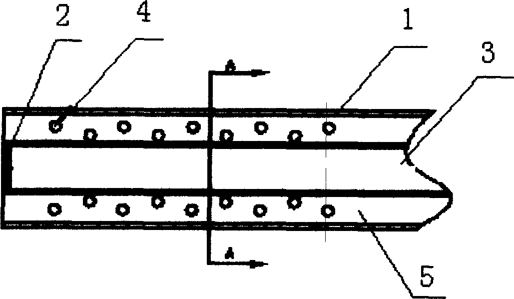
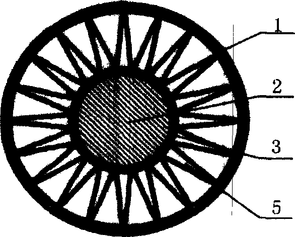
[0012] see figure 1 , 2. The present invention includes an external base pipe 1, an internal core pipe 3 with both ends plugged 2, and 2 to 30 corrugated fins 5 uniformly arranged along the circumference of the internal core pipe 3. On the side of the corrugated fins 5 There are through holes 4 on the wall. Since the through holes 4 are opened on the corrugated fins 5 , the flow channel is an incompletely separated annular channel, and the perforated corrugated fin runs through the entire flow channel in the annular flow tube.

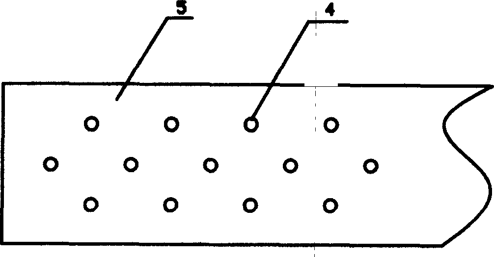
[0013] see image 3 According to the present invention, the corrugated fins 5 are provided with through holes 4 with a hole pitch of 10 mm and a diameter of 3 mm.

[0014] The corrugated fin 5 of the present invention adopts a straight edge, which is convenient to manufacture, and the gas flow resistance will not increase significan...


PUM


Abstract

The invention disclose a intensive heat conducting tube applied to high mucosity liquor cooler, heater or cooling device in air compressor on energy, power, fossil, chemistry fields. It comprises exterior basal tube, inner core tube with two ends jamming and wave wing fins set between the inner core tube and exterior basal tube arranged along inner core tube uniformly. Set two or more through holes on the side wall of the wave wing fins. In consequence that there are holes on the wave wing fins, the inner flowing channel of the tube is a non-complete-separated round flowing channel. The inner wing fin with holes increases the flowing speed gradient with disturbing the border layer improving the association between fluid speed and the temperature gradient. Meanwhile due to the number of fins and the holes on the fins, the heat exchanger performance is enhanced so to lower the size of heat exchanging device and lower the production cost.

Description

technical field [0001] The invention relates to an enhanced heat exchange tube, in particular to an enhanced heat exchange tube used in high-viscosity fluid coolers (such as oil coolers), heaters, or intercoolers of air compressors in the fields of energy, power, petroleum, and chemical industry. Heat pipe. Background technique [0002] In high-viscosity fluid coolers, heaters or intercoolers of air compressors, in order to enhance the heat transfer in the tubes, inner fins are installed in the tubes to increase the heat transfer area and reduce the thermal resistance of the fluid. However, in the currently used light pipes, along the direction of fluid flow, the boundary layer formed by the fluid on the surface of the fins will gradually thicken, making the coordination between the velocity and temperature gradient worse, thereby reducing the heat transfer performance. In order to further improve the heat transfer performance of the finned tube heat exchanger, an inner fin...

Claims


Application Information

Patent Timeline
Patent Type & Authority Applications(China)
IPC IPC(8): F28F1/14
Inventor 陶文铨何雅玲屈治国
Owner XI AN JIAOTONG UNIV
Why Eureka
Try Eureka