Electromagnetic coil of step-by-step motor of electric valve

A technology of stepping motor and electromagnetic coil, applied in the direction of electric components, valve operation/release device, valve device, etc., can solve the problems of labor-hour and cost, increase cost, etc. cost effect

Inactive Publication Date: 2005-10-05
FUJIKOKI MFG CO LTD
View PDF1 Cites 4 Cited by
  • Summary
  • Abstract
  • Description
  • Claims
  • Application Information

AI Technical Summary

Problems solved by technology

[0005] However, in such a method of fixing the pole teeth structural parts of the electric valve, since the antirust plating layer of the stator cover is peeled off due to welding, riveting

Method used


Image

  • Electromagnetic coil of step-by-step motor of electric valve
  • Electromagnetic coil of step-by-step motor of electric valve
  • Electromagnetic coil of step-by-step motor of electric valve

Examples


Embodiment 1

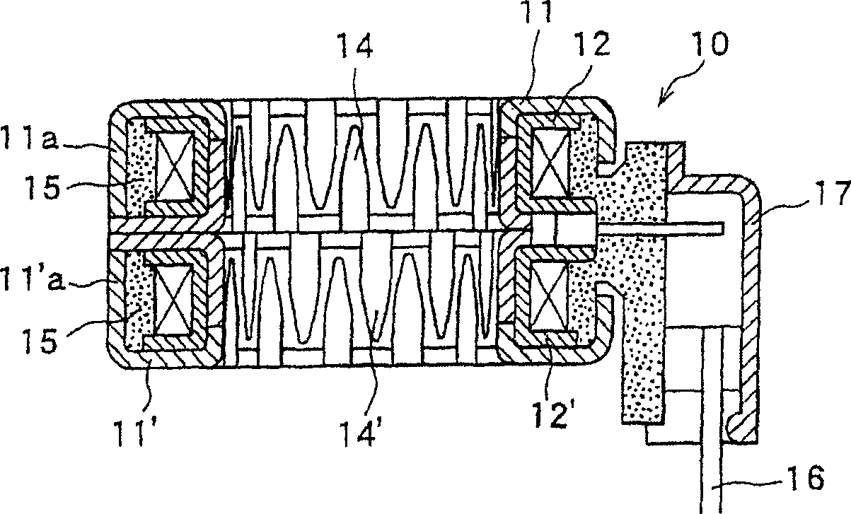
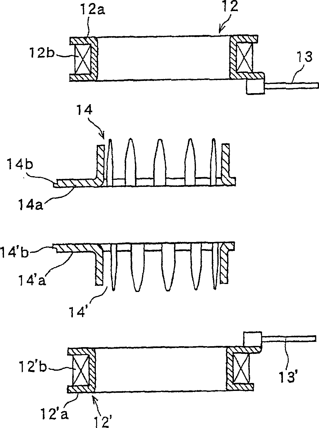
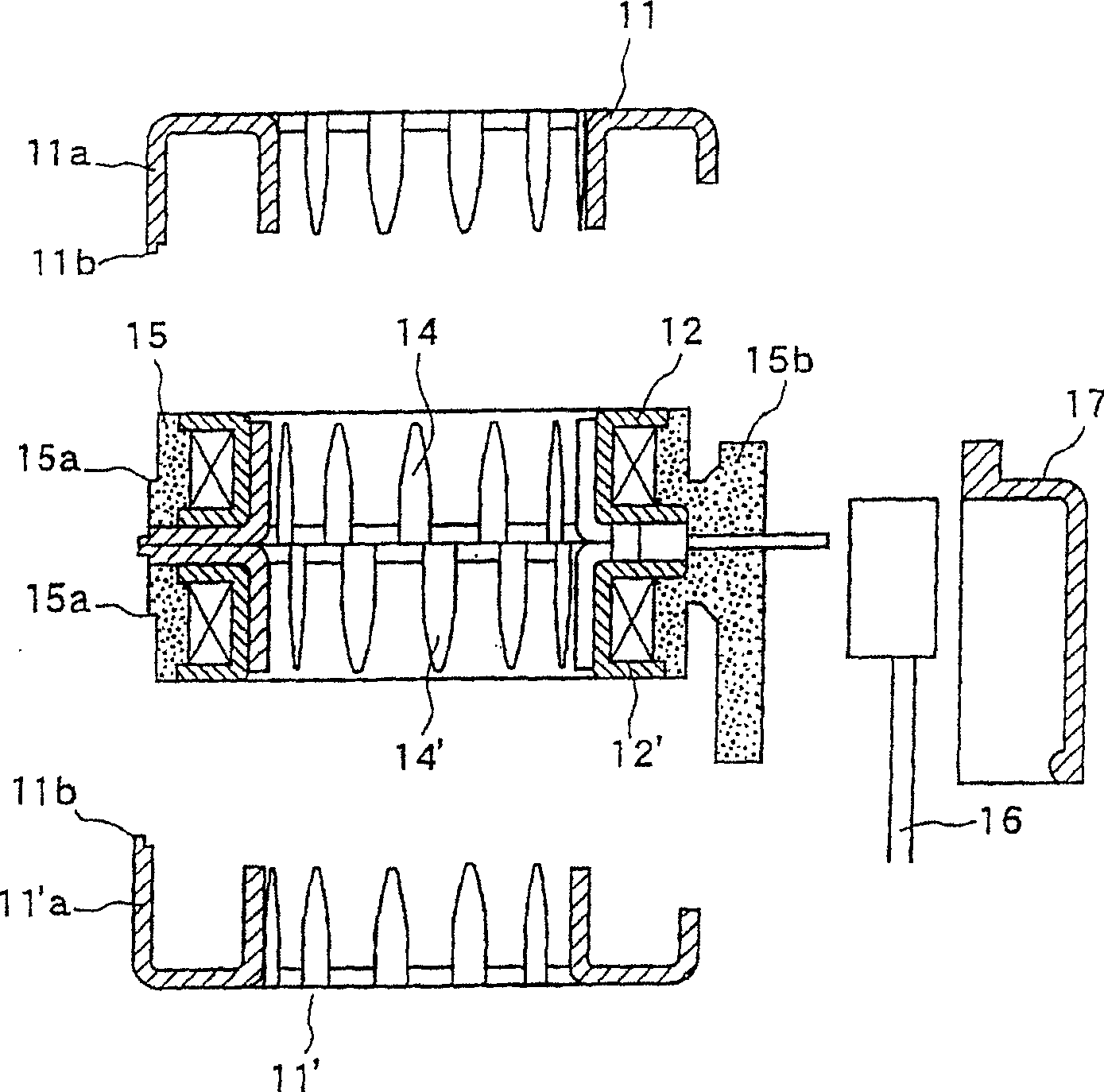
[0033] Embodiment 1 will be described with reference to the drawings. figure 1 is a longitudinal sectional view of the electromagnetic coil, figure 2 It is a cross-sectional view showing the first stage of the assembly process of the same electromagnetic coil, image 3 is a sectional view showing the second stage, Figure 4 It is an explanatory diagram showing important parts of the same assembly process.

[0034] The electromagnetic coil 10 of the stepping motor, such as figure 1 As shown, by winding the first coil 12b on the first bobbin main body 12a, and covering the outer peripheral portion of the first coil 12b with the resin molded part 15, the first bobbin part 12 is formed on the second bobbin main body 12 The second coil 12'b is wound on the 'a, and the second coil frame part 12' which covers the outer peripheral part of the second coil 12'b with the resin molded part 15 is sandwiched between the first coil frame part 12 and the second coil frame part 12'. The...

Embodiment 2

[0043] Hereinafter, Embodiment 2 will be described with reference to the drawings. Figure 5 is a longitudinal sectional view of the electromagnetic coil, Image 6 is a cross-sectional view showing the first stage of the assembly process of the electromagnetic coil, Figure 7 It is a sectional view showing the second stage of the same assembly process, Figure 8 It is an explanatory diagram showing important parts of the same assembly process, Figure 9 It is a plan view of the electromagnetic coil of Example 2.

[0044] The electromagnetic coil 20 of the stepping motor is as Figure 5 As shown, by winding the first coil 22b on the first bobbin main body 22a and covering the outer peripheral portion of the first coil 22b with the resin molded part 25, the second bobbin main body 22 The second coil 22'b is wound on the 'a, and the second coil frame part 22' which covers the outer peripheral part of the second coil 22'b with the resin molded part 25 is sandwiched between the...

Embodiment 3

[0052] Hereinafter, Embodiment 3 will be described with reference to the drawings. Figure 10 It is a longitudinal sectional view of the electromagnetic coil of this embodiment 3, Figure 11 is a cross-sectional view showing the first stage of the assembly process of the electromagnetic coil, Figure 12 It is a sectional view showing the second stage, and FIG. 13 is a plan view of the electromagnetic coil of Embodiment 3, Figure 14 It is an explanatory diagram showing important parts of the same assembly process.

[0053] The electromagnetic coil 30 of the stepping motor is as Figure 10 As shown, by winding the first coil 32b on the first coil body 32a and covering the outer peripheral portion of the first coil 32b with the resin molded part 35, the second coil body 32 The second coil 32'b is wound on 'a, and the second bobbin part 32' which covers the outer peripheral part of the second coil 32'b with the resin molded part 35 is sandwiched between the first coil bobbin p...


PUM


Abstract

The electromagnetic coil of the present invention has a first bobbin portion in which a first coil (12b) is wound on a first bobbin main body (12a), and the outer peripheral portion of the first coil (12b) is covered with a resin molded part (15). (12), wind the second coil (12'b) on the second bobbin main body (12'a), and cover the second coil (12'b) outer peripheral part with the resin mold casting (15). Coil frame part (12'), two magnetic pole plates (14, 14') sandwiched between the first coil frame part and the second coil frame part; formed on the first and second coil frame parts or resin molded parts The protruding part (15a) is used as a mechanism for respectively covering and fixing the stator cover (11, 11') on the first bobbin part (12) and the second bobbin part (12'), and using the protruding The output portion (15a) applies ultrasonic waves to make it deformable and integrated.

Description

technical field [0001] The present invention relates to an electromagnetic coil of a stepping motor of an electric valve used in the refrigerating cycle of an air conditioner and a refrigerating device. Background technique [0002] Conventionally, such a stepping motor solenoid incorporated in an electric valve used in an air conditioner, a refrigerator, etc. is disclosed as a conventionally known electric valve in the following Patent Document 1 - Japanese Unexamined Patent Application Publication No. 2001-86684. [0003] Now refer to Figure 15 The electric valve disclosed in this Patent Document 1 will be described. Figure 15 It shows the longitudinal sectional view of the electric valve. The characteristic of the solenoid coil of the stepping motor of the electric valve 1 is that the coil A (1b) is wound on the main body A (1a) of the bobbin, and the coil is used to communicate with the external The connected terminal pin A (1c) is integrated with the bobbin main body ...

Claims


Application Information

Patent Timeline
IPC IPC(8): F16K31/04H02K3/46H02K37/14
Inventor 菅沼威大内共存
Owner FUJIKOKI MFG CO LTD
Why Eureka
Try Eureka