
Piezoelectric executor driving power supply

A technology for piezoelectric actuators and driving power sources, applied in the direction of generators/motors, piezoelectric effect/electrostrictive or magnetostrictive motors, electrical components, etc., can solve problems that cannot meet piezoelectric actuators, and achieve The effect of low cost, fast response and convenient debugging

Inactive Publication Date: 2005-10-05
INST OF ELECTRONICS CHINESE ACAD OF SCI
View PDF0 Cites 5 Cited by
  • Summary
  • Abstract
  • Description
  • Claims
  • Application Information

AI Technical Summary

Problems solved by technology

However, the traditional piezoelectric ceramic drive power supply only has the function of one-way charging and discharging, which cannot meet the needs of most piezoelectric actuators.

Method used


Image

  • Piezoelectric executor driving power supply
  • Piezoelectric executor driving power supply

Examples


Embodiment Construction

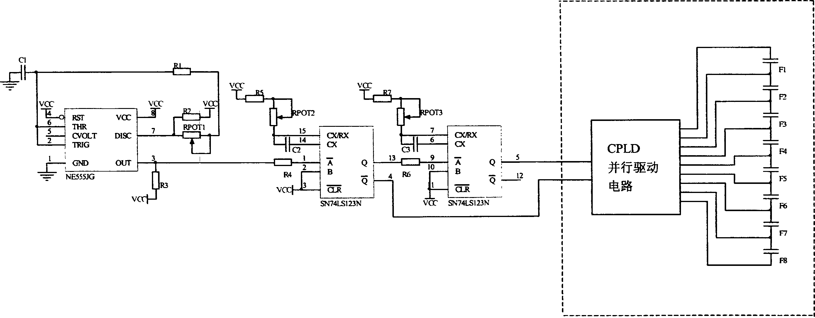
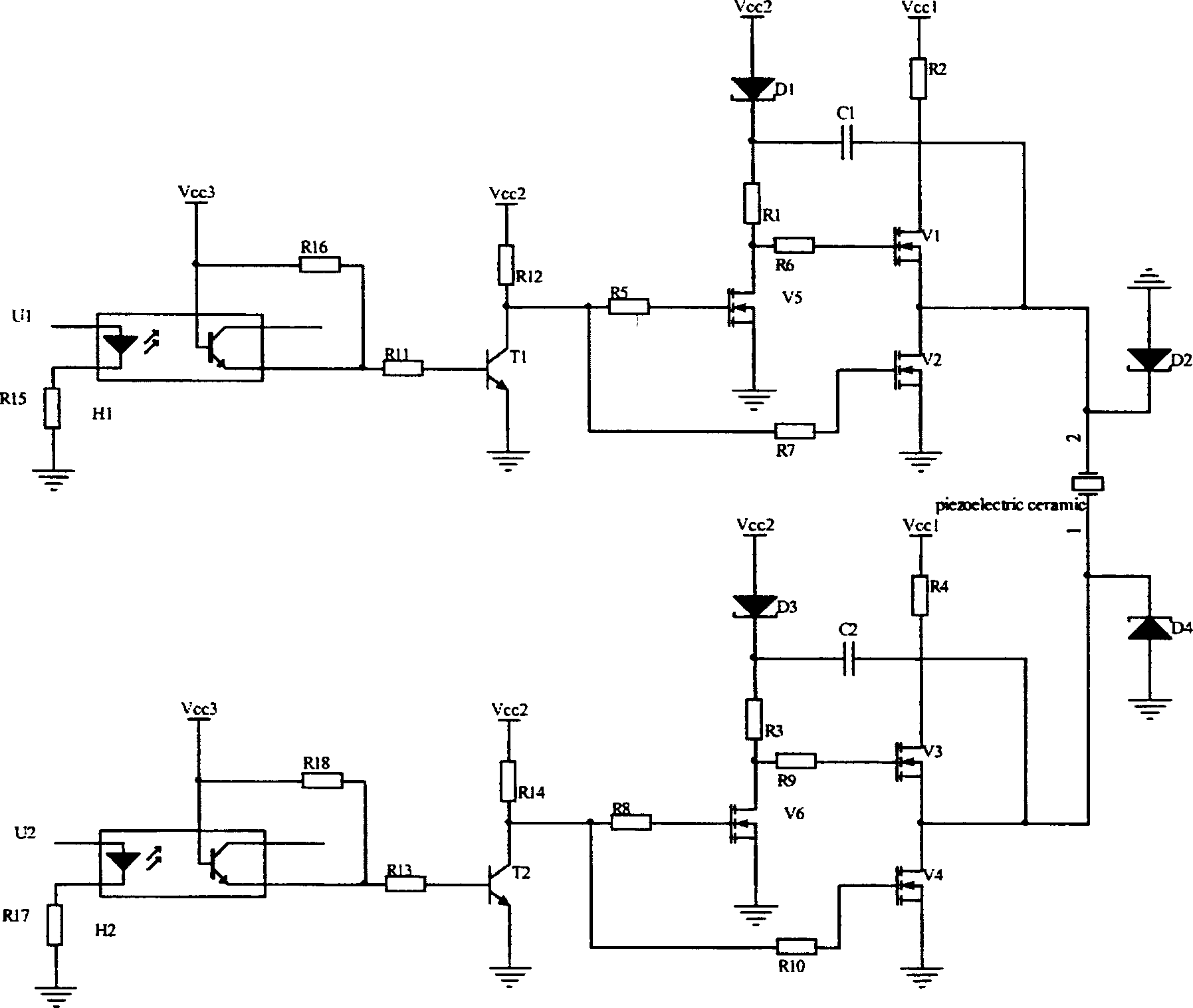
[0023] Combine below figure 1 and figure 2 An embodiment of the present invention is described in detail.

[0024] Such as figure 1 As shown, the driving power supply of the present invention is composed of a control circuit and an amplifying circuit. The n-way output (n≥2) of the control circuit is used as the input of the amplifying circuit, and the n-way output of the amplifying circuit is connected to n-1 loads . The amplifying circuit is composed of a plurality of identical amplifying sub-circuits, and the number of amplifying sub-circuits is equal to the number of input signals of the amplifying circuit.

[0025] The control circuit can generate n channels (n≥2) of pulse waveforms that satisfy a specific time sequence relationship with each other. After being amplified by the amplifier circuit, n-1 loads can be driven in parallel.

[0026] figure 2 As an embodiment of the present invention, it can drive 2 loads in parallel. The control circuit of this embodiment...


PUM


Abstract

The drive power source comprises control circuit part and amplification circuit part. The control circuit part can generate impulse waveform in n routes of satisfying specific time sequence relation between each other. The amplification circuit part comprises identical sub amplification circuits. Number of sub amplification circuits is equal to number of input signals of amplification circuit part. Output of the control circuit part is as input of the amplification circuit part. Output of the amplification circuit part can drive m pieces of load. The said output can charge moving elements of actuator to carry out charging and discharging in both positive and negative directions. Advantages are: high output voltage, large current loading capacity, adjustable pulse frequency and pulse width of control signal, driving multiple moving elements in parallel.

Description

technical field [0001] The invention relates to the technical field of power supplies, in particular to a driving power supply for piezoelectric actuators. Background technique [0002] Using the inverse piezoelectric effect of piezoelectric ceramics, various piezoelectric actuators can be made. Most piezo actuators have moving parts that can move in both forward and reverse directions. That is, when +c volts are applied, +x displacement can be produced at a certain point; if -c volts are applied, -x displacement can be produced at the same point. This requires that the driving power supply of the piezoelectric actuator can not only charge the moving parts forwardly, but also reversely charge them. However, the traditional piezoelectric ceramic drive power supply only has the function of one-way charging and discharging, which cannot meet the needs of most piezoelectric actuators. Contents of the invention [0003] The purpose of the present invention is to overcome the...

Claims


Application Information

Patent Timeline
Patent Type & Authority Applications(China)
IPC IPC(8): H02N2/06H02N2/14
Inventor 崔大付许立宁
Owner INST OF ELECTRONICS CHINESE ACAD OF SCI
Learn More