V-belt type variable speed drive

A belt-type continuously variable speed and pulley technology, applied in the directions of portable lifting devices, hoisting devices, transmission devices, etc., can solve the problems of offset, maximum speed reduction, and larger winding diameter.

Inactive Publication Date: 2005-10-05
YAMAHA MOTOR CO LTD
View PDF2 Cites 9 Cited by
  • Summary
  • Abstract
  • Description
  • Claims
  • Application Information

AI Technical Summary

Problems solved by technology

[0004] However, in the case of adopting a structure that restricts the speed reduction ratio at the top end on the drive pulley side like the above-mentioned conventional device, the winding diameter of the drive pulley becomes smaller in accordance

Method used


Image

  • V-belt type variable speed drive
  • V-belt type variable speed drive
  • V-belt type variable speed drive

Examples


Embodiment Construction

[0029] Embodiments of the present invention will be described below with reference to the drawings.

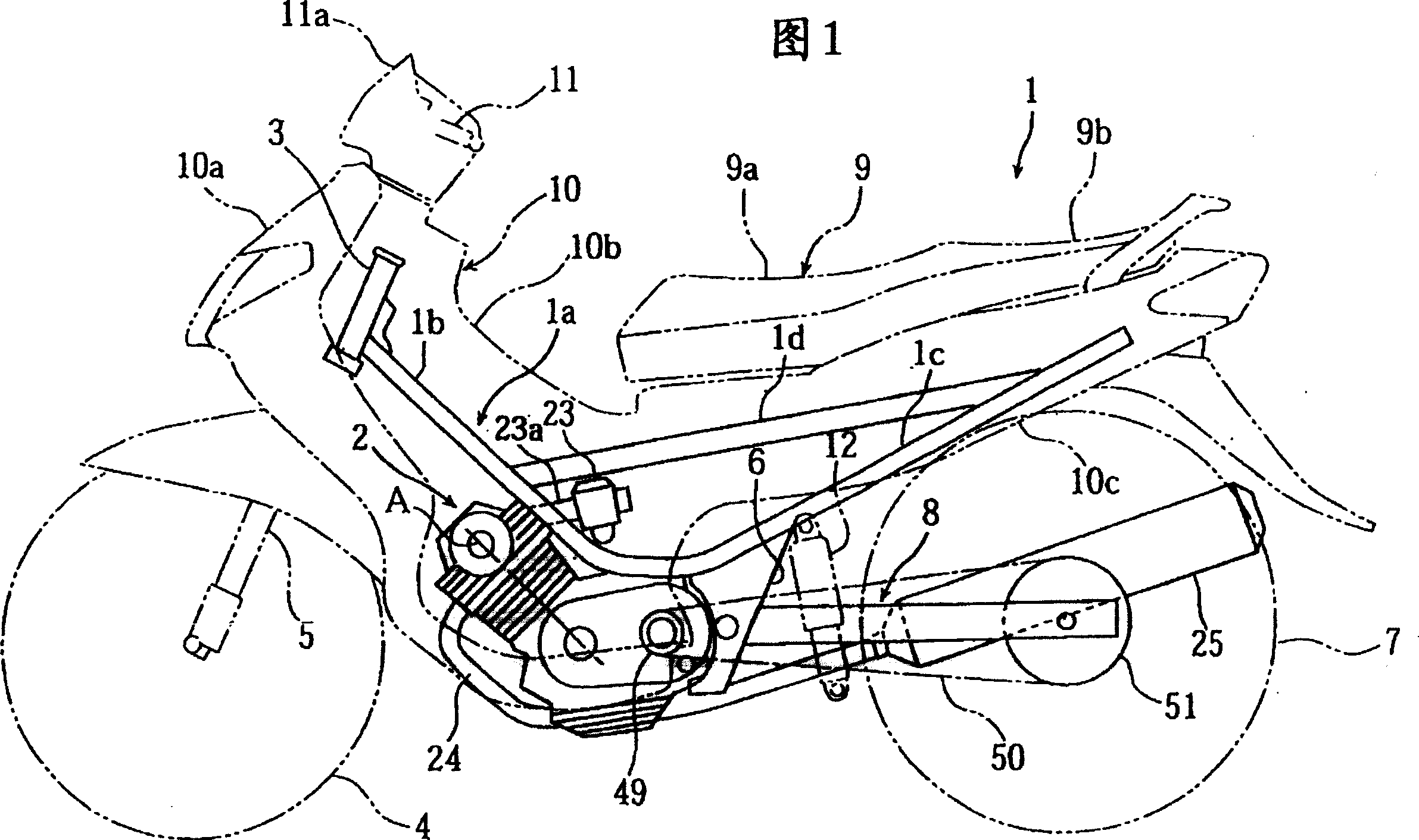
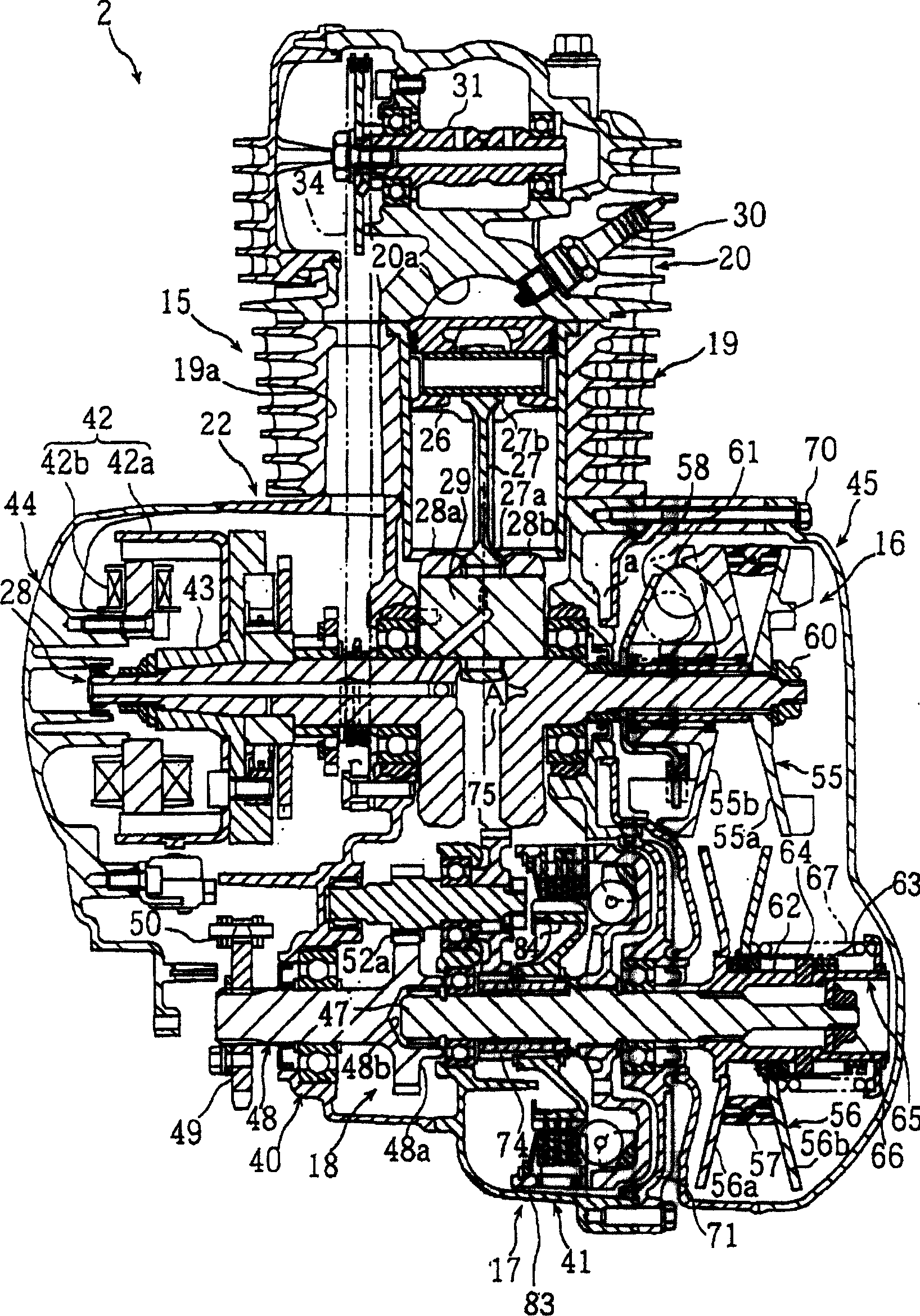
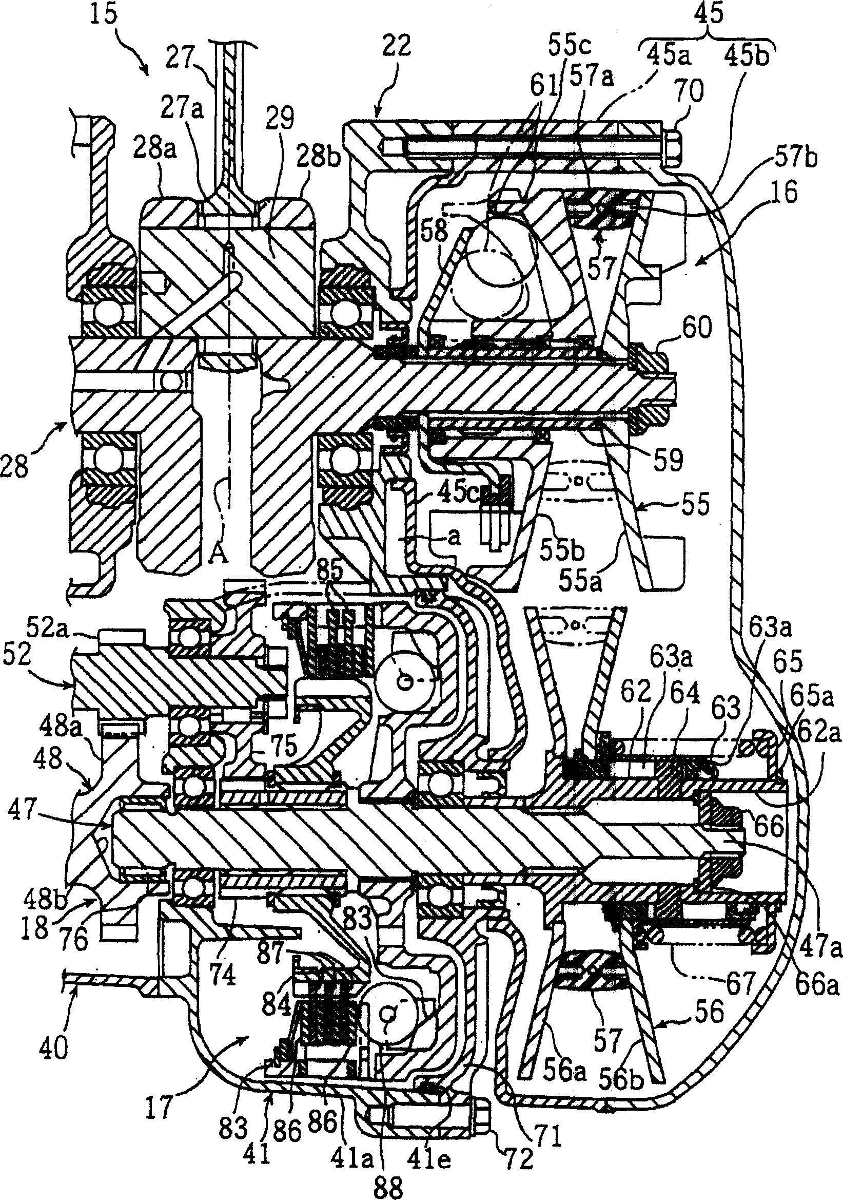
[0030] Figure 1 to Figure 6 It is a figure for demonstrating the V-belt type continuously variable transmission device which concerns on one Embodiment of this invention. FIG. 1 is a left side view of a motorcycle equipped with a V-belt type continuously variable transmission according to the present embodiment, figure 2 It is a sectional plan view of an engine unit equipped with a V-belt type continuously variable transmission, image 3 It is a cross-sectional plan view of a V-belt continuously variable transmission, Figure 4 , Figure 5 , Figure 6 are cross-sectional views showing changes in the winding diameter due to wear of the V-belt. In addition, front and rear and left and right referred to in this embodiment mean front and rear, left and right seen in the state of sitting on the seat.

[0031] In FIG. 1, 1 denotes a two-wheeled motor vehicle, which generally...


PUM


Abstract

In a V belt type continuously variable transmission constituted by coupling a drive pulley 55, which is mounted on a crankshaft (input shaft) 28, and a driven pulley 56, which is mounted on a transmission shaft (output shaft) 47, with a V belt 57, when a driven side variable pulley half body 56b of the driven pulley 56 moves to a top time position where a winding diameter is minimized, a boss portion 63 of the driven side movable pulley half body 56b is brought into abutment against a spring bearing member 65, whereby the driven side movable pulley half body 56b is regulated to the top time position.

Description

technical field [0001] The present invention relates to a V-belt type continuously variable transmission in which a driving pulley mounted on an input shaft for transmitting rotational force and a driven pulley mounted on an output shaft are connected by a V-belt. Background technique [0002] For example, in a small two-wheeled motor vehicle (scooter), a V-belt type continuously variable transmission may be used as a power transmission mechanism for transmitting engine power to the rear wheels. In this V-belt type continuously variable transmission device, such as Figure 13 As shown in (a) and (b), it is generally a structure in which the driving pulley 103 and the driven pulley 107 are connected by a V-belt 108, wherein the driving pulley 103 is installed on the crankshaft (input shaft) 100 and has a drive side fixed pulley half body 101 and driving side movable pulley half body 102; Body 106. [0003] In the above-mentioned V-belt type continuously variable transmissio...

Claims


Application Information

Patent Timeline
IPC IPC(8): F16H9/18F16H55/56F16H61/662F16H63/06
CPCF16H2061/66295F16H63/067F16H55/56F16H9/18
Inventor 石田洋介
Owner YAMAHA MOTOR CO LTD
Why Eureka
Try Eureka