
Motor rotor

A technology for electric motors and rotors, applied in the manufacture of stator/rotor bodies, synchronous motors with stationary armatures and rotating magnets, electromechanical devices, etc., can solve the problems of increased component costs and troublesome assembly operations, and achieve cost reduction and assembly Easier, torque-enhancing effect

Inactive Publication Date: 2005-10-12
NIDEC SHIBAURA CORP
View PDF1 Cites 6 Cited by
  • Summary
  • Abstract
  • Description
  • Claims
  • Application Information

AI Technical Summary

Problems solved by technology

[0005] Eccentricity of the outer peripheral side of the magnet 104 in this way can facilitate self-starting, but when assembling the rotor 100, since the magnet 104 must be attached in an eccentric state, and the pole piece 106 must be attached, so the assembly operation becomes easier. trouble
[0006] In addition, since the pole piece 106 must be mounted, there is also a problem of increased component costs.

Method used


Image

  • Motor rotor
  • Motor rotor
  • Motor rotor

Examples


Embodiment Construction

[0021] (first embodiment)

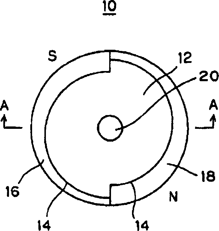
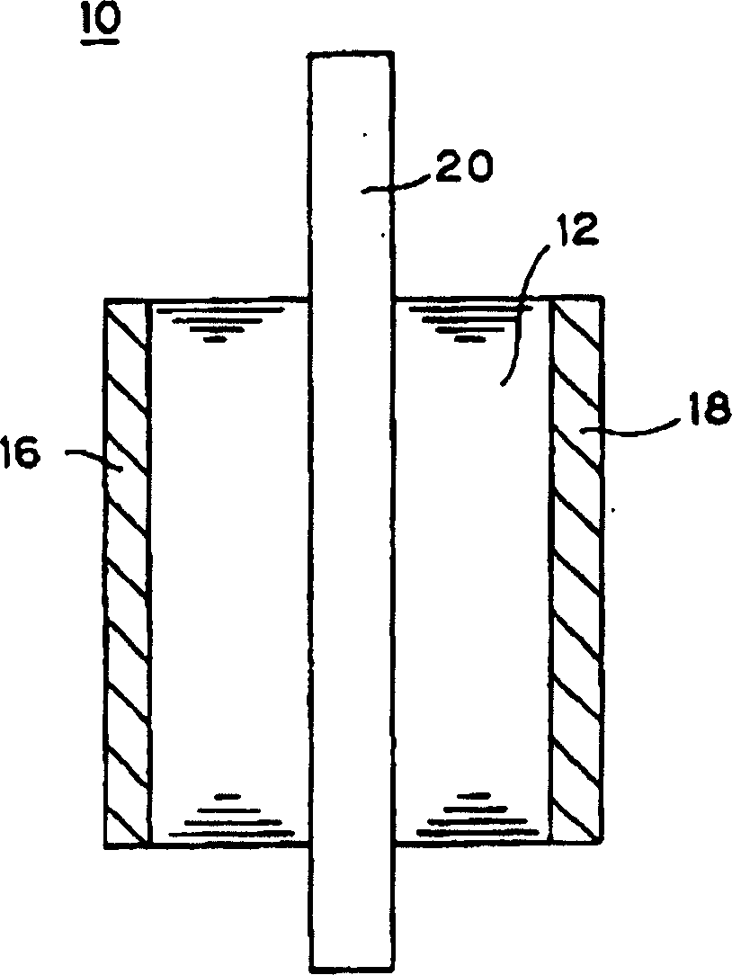
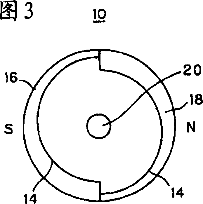
[0022] Below, refer to figure 1 and figure 2 The rotor 10 according to the first embodiment of the present invention will be described.

[0023] The rotor 10 of the present embodiment is a rotor of a single-phase synchronous motor, and has a two-pole configuration of an S pole and an N pole.

[0024] The structure of the rotor 10 will be described together with the manufacturing method.

[0025] As a first manufacturing process, steel plates are laminated and caulked to manufacture the rotor core 12 . Here, if figure 1 As shown, when the planar shape of the rotor core 12 is divided into left and right with the rotation axis as the center, the left part has an arc shape that is eccentric with respect to the rotation axis, and the right part is eccentric in a direction different from the left part. Oval. And, two spiral recesses 14, 14 are provided by this eccentricity.

[0026] As a second manufacturing process, the rotor core 12 is housed ...


PUM


Abstract

The present invention is to provide a rotor of a motor capable of facilitating self-start and assembling work. A plastic magnet 16 magnetized with the S pole on the outer circumferential side of a rotor 10 and a plastic magnet 18 magnetized with the N pole on the outer circumferential side of the rotor 10 are provided alternately on the outer circumferential surface of a rotor core 12. The plastic magnets 16, 18 of the poles have spiral cross-sectional shapes which are made eccentric on the inner circumferential side, thus enhancing starting torque.

Description

technical field [0001] The present invention relates to rotors of motors such as single-phase synchronous motors and brushless DC motors. Background technique [0002] In the rotor of a motor such as a brushless DC motor, magnets are arranged such that S poles and N poles alternate to obtain magnetic force (see, for example, Patent Document 1). [0003] Patent Document 1: Japanese Patent Laid-Open No. 2004-48827 [0004] In single-phase synchronous motors, in order to facilitate self-starting, such as Figure 5 As shown, the magnet 104 is mounted eccentrically on the outer peripheral portion of the rotor core 102 of the rotor 100 . In addition, a pole piece 106 made of a high magnetic permeability material is attached to the outer peripheral side of the magnet 104 so that the outer peripheral portion of the rotor 100 has a circular shape. [0005] Eccentricity of the outer peripheral side of the magnet 104 in this way can facilitate self-starting, but when assembling the r...

Claims


Application Information

Patent Timeline
IPC IPC(8): H02K1/22H02K1/27H02K15/03H02K21/12H02K21/14H02K29/00
CPCA61B17/32093A61B2017/00747A61B2017/320008A61M2202/092A61M1/84
Inventor 吉田洋
Owner NIDEC SHIBAURA CORP
Learn More