
Spotlight

A spotlight and light source technology, which is applied in the field of spotlights, can solve problems such as the increase of spotlights, obstacles to miniaturization of spotlight structures with high power spotlights, and unsatisfactory fans.

Inactive Publication Date: 2005-10-12
ANOLD RIBUTT MOVIE TECH
View PDF0 Cites 0 Cited by
  • Summary
  • Abstract
  • Description
  • Claims
  • Application Information

AI Technical Summary

Problems solved by technology

However, the increased surface area on the spotlight housing obtained in this way leads to an overall increase in the spotlight and thus constitutes an obstacle to the miniaturization of the construction of spotlights, especially high-power spotlights
[0004] Installing a fan to dissipate the heat load is not ideal in many cases due to the noise it produces

Method used


Image

  • Spotlight
  • Spotlight
  • Spotlight

Examples


Embodiment Construction

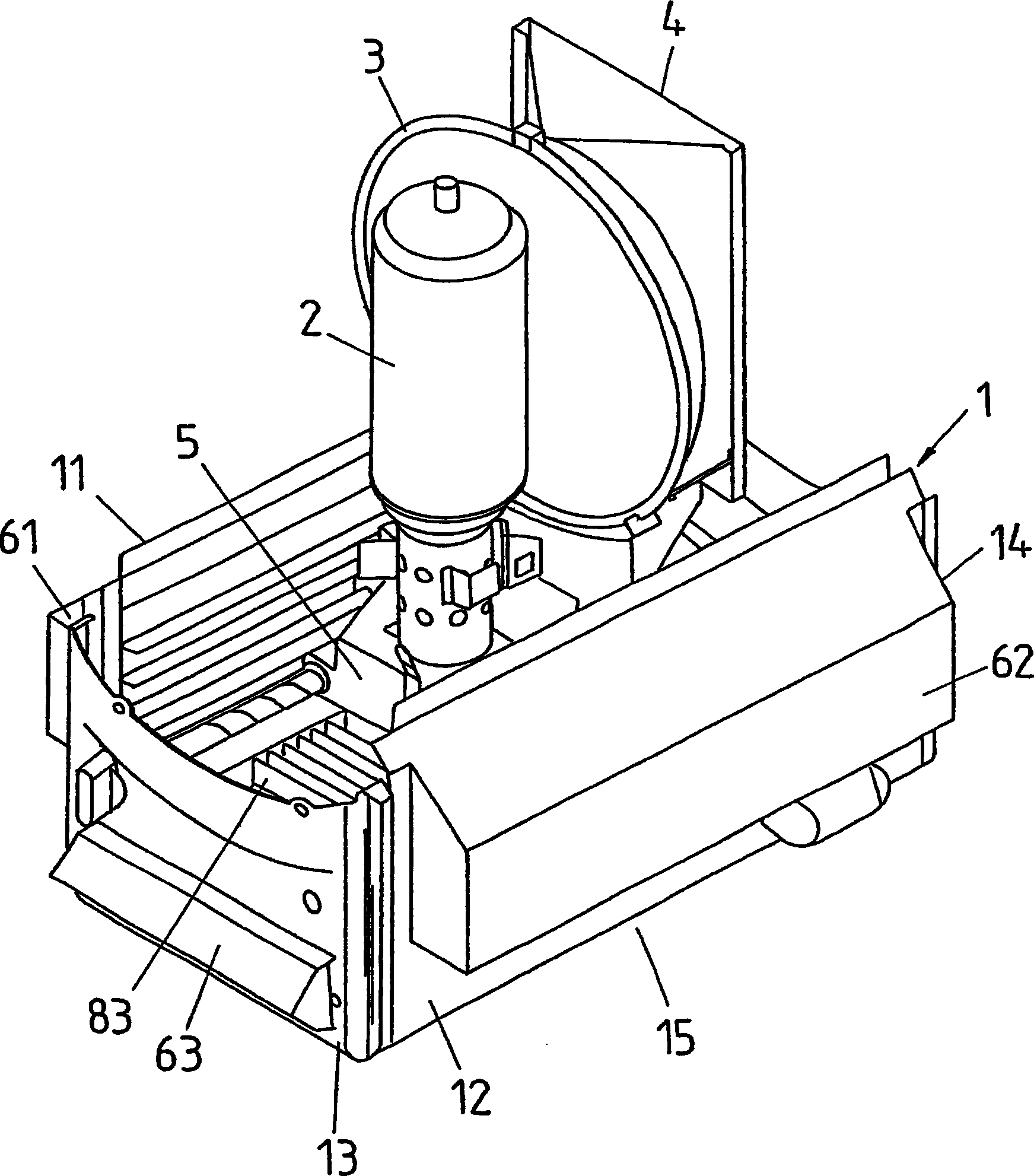
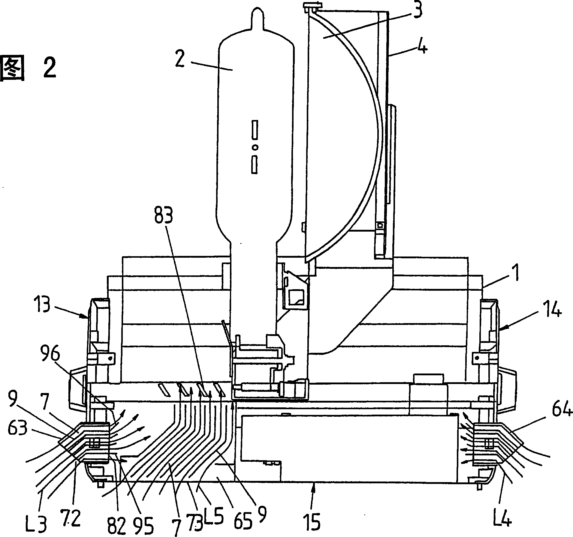
[0027] figure 1 The perspective view in shows a part of the spotlight, wherein the lower part of the spotlight housing 1 is equipped with a light source 2 and a reflector 3, the light source 2 is assembled in the light source seat 5 connected to the spotlight housing 1, and the reflector 3 is connected to a It is also fixed on the reflector frame 4 on the spotlight housing 1 . The light source 2, the reflector 3 and the reflector holder 4, which are designed in the form of a bulb or lamp, are surrounded by a generally cylindrical upper housing part of the spotlight, which is connected to the lower housing part of the housing of the spotlight 1 , and a cover element in the form of a glass disc or lens is installed at the front, and the end opposite to the cover element is closed. The upper spotlight housing section is constructed with a regular profile to increase the heat dissipation surface.

[0028] The lower part of the light source housing 1 is substantially square, and ...


PUM


Abstract

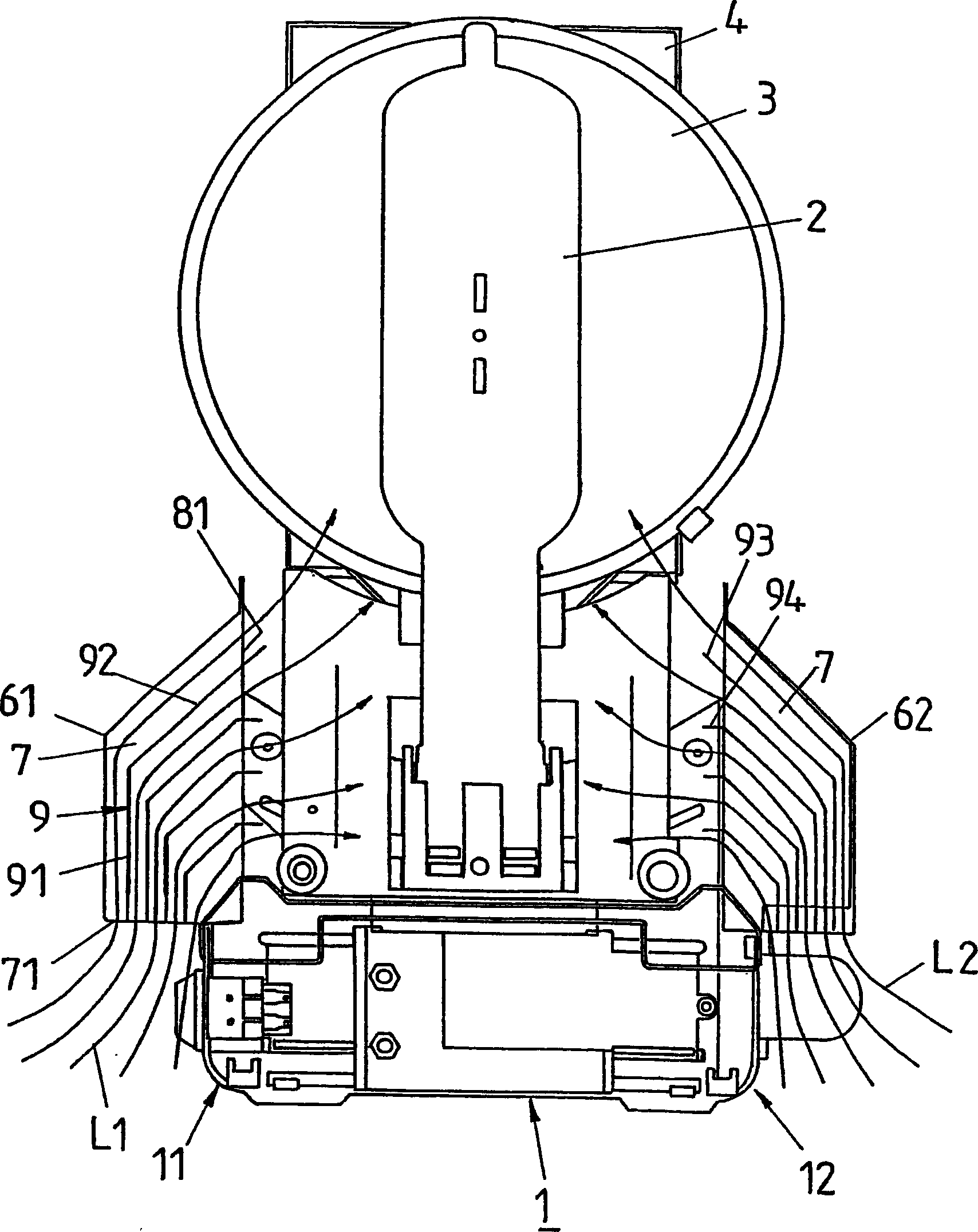
The invention relates to a projector, particularly a stage projector, studio projector, film projector, and / or television projector, comprising a light source and a projector housing that surrounds the light source and is provided with a translucent covering element. At least one wall (11 to 15) of the inventive projector housing (1) comprises a ventilation shaft (61 to 63) with separate ventilation ducts (7).

Description

technical field [0001] The invention relates to a spotlight according to the preamble of claim 1 , in particular a spotlight for the stage, studio, film or television industry. Background technique [0002] Spotlights of this type have a single or two-seat light source mounted in the spotlight housing and comprising a bulb or burner, for example a discharge lamp in the form of a metal halide or sodium high pressure vapor lamp, which passes through a A reflector, also mounted in the spotlight housing, emits light through an opening in the spotlight housing. In order to protect the light source and / or adjust the shape of the reflected light, the spotlight housing is closed at its front by a preferably translucent cover element, which uses a protective disc or disc held in a frame or seat The form of the lens. [0003] In addition to reflecting the part of the light visible to the human eye, thermal radiation in the infrared spectrum is also emitted, and the thermal radiation...

Claims


Application Information

Patent Timeline
IPC IPC(8): F21S8/00F21V29/00
CPCF21W2131/406F21V29/2293F21V29/004F21V29/83
Inventor 托马斯·德尔纳
Owner ANOLD RIBUTT MOVIE TECH
Learn More