Electronic ballast with charge pump for active power factor calibration

A ballast and power rectifier technology, applied in the field of pump circuits, can solve problems such as expensive and achieve the effect of high power factor

Inactive Publication Date: 2005-10-12
TRIDONIKATKO GMBKH & KO KG
View PDF1 Cites 6 Cited by
  • Summary
  • Abstract
  • Description
  • Claims
  • Application Information

AI Technical Summary

Problems solved by technology

This active PFC circuit has a higher efficiency than traditional passive PFC circuits, but is actua...

Method used


Image

  • Electronic ballast with charge pump for active power factor calibration
  • Electronic ballast with charge pump for active power factor calibration
  • Electronic ballast with charge pump for active power factor calibration

Examples


Embodiment Construction

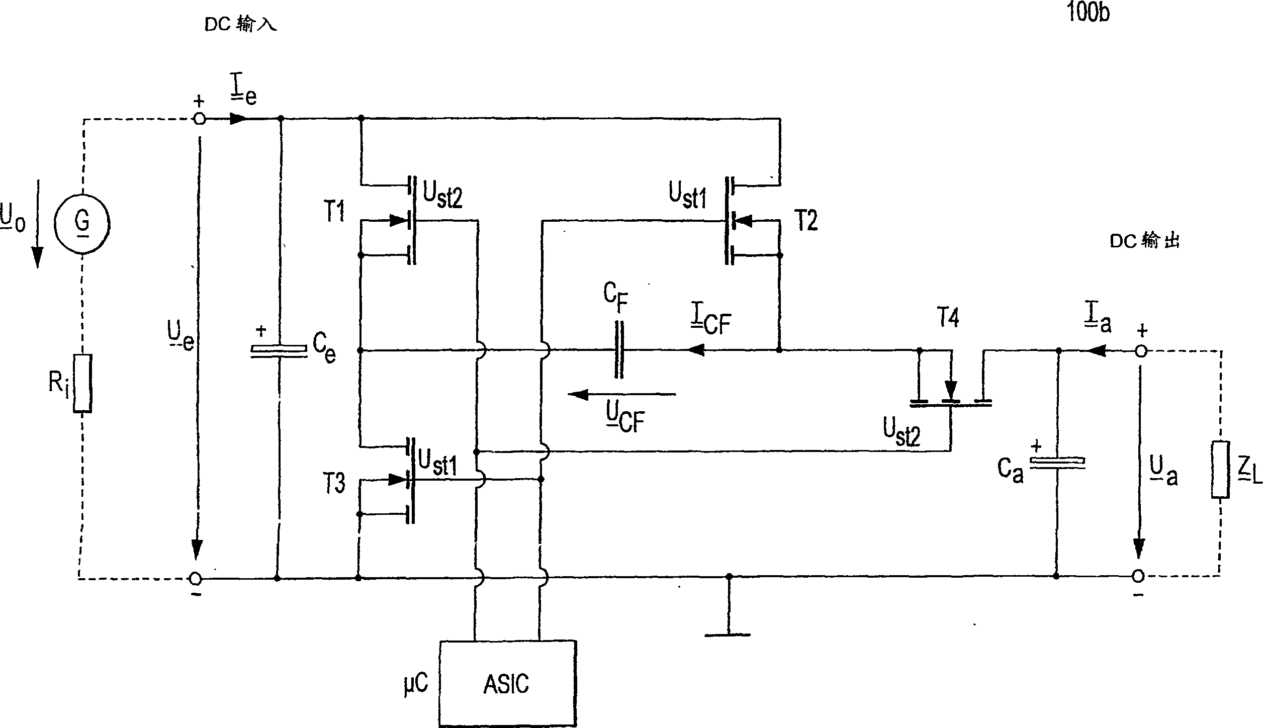
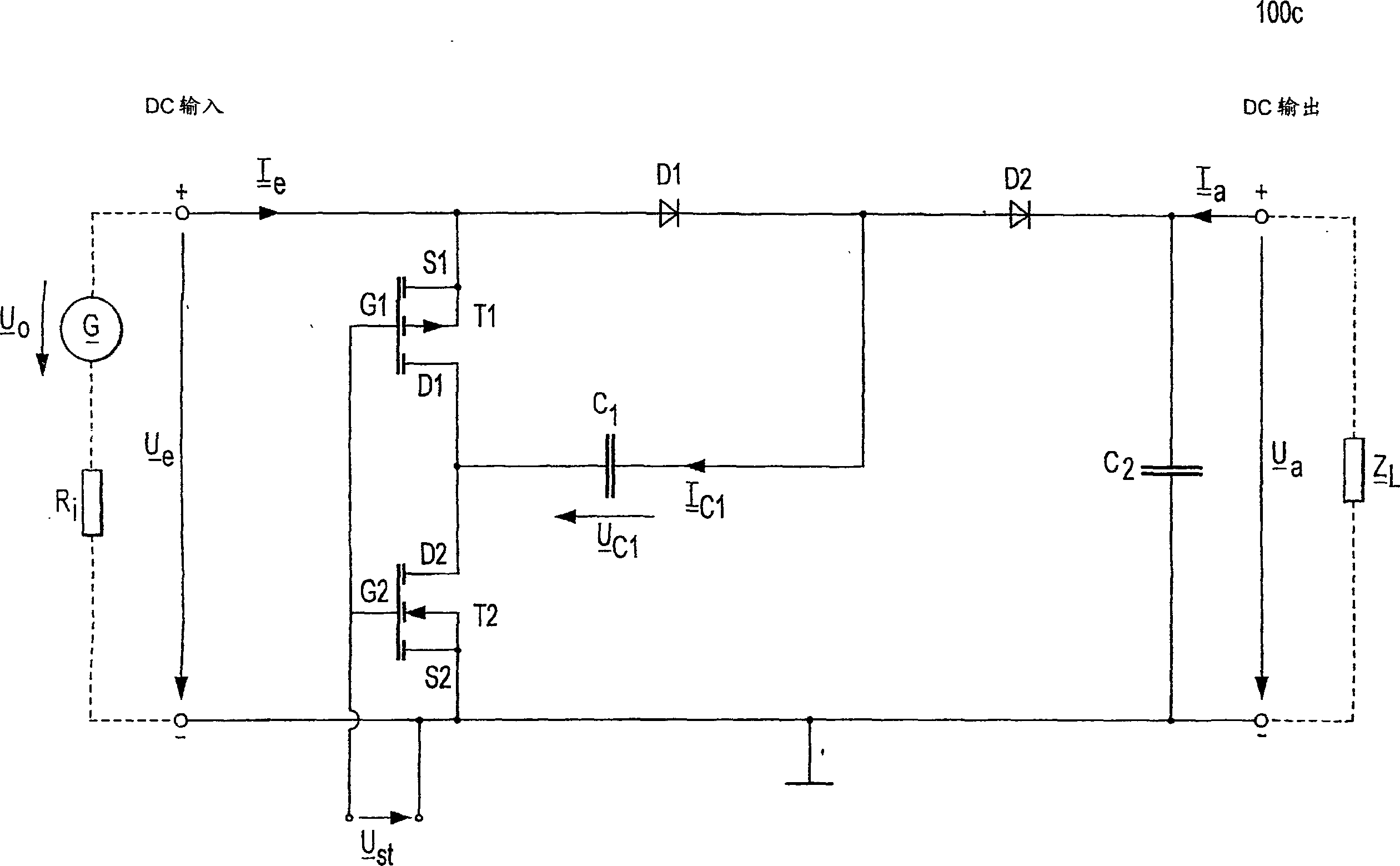
[0053] The following will describe in more detail what is included in the Figure 3a and 3b Functions of the elements in two exemplary embodiments of an active PFC circuit for an electronic ballast (EVG) for low-voltage gas discharge according to the invention shown in .

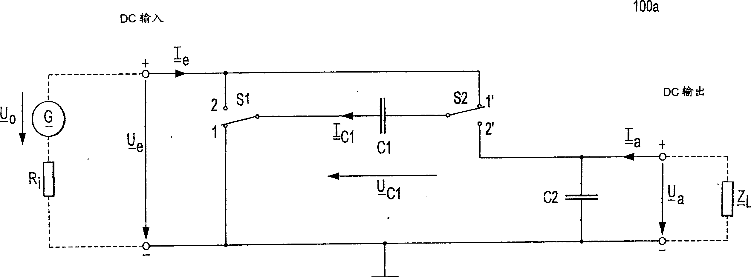
[0054] Figure 3a A first embodiment of an active PFC circuit 300a according to the invention shown in has a mains rectifier AC / DC implemented as a rectifier full bridge or as a multiplex rectifier for the a.c. voltage U supplied from a current source Netz rectification; storage capacitor C1, connected in parallel with the mains rectifier AC / DC and realized as an electrolytic capacitor (Elko), for obtaining a rectified and smoothed first intermediate circuit voltage U C1 ; with the harmonic filter OWF, connected to this storage capacitor, including along the pulsating d.c. current supplied from the mains rectifier AC / DC I D The two rectifier diodes D1 and D2 set in the forward direction of ; and the pum...


PUM


Abstract

The invention relates to a pump circuit (300a+b), which serves as a charge pump while being provided for an electronic ballast (EVG) for the high-frequency operation of one or more series-connected low-pressure gas discharge lamps (LA1, LA2). Said ballast serves to rectify the alternating voltage (UNetz) supplied by a power supply mains, to filter mains harmonic waves, and to carrying out a method, which is based on an expanded Active Valley Fill (AVF) principle and which is provided for correcting the power factor lambda (PFC) in order to enable an approximate sinusoidal current consumption, for example, in accordance with IEC Standard 1000-3-2. To this end, a pump capacitor (C2) of a pump circuit (300a+b) is supplied with power by the galvanically separated decoupling of the current flowing through the lamp so that when the lamp fails, the pump mechanism automatically comes to a standstill whereby eliminating the problem of load shedding.

Description

technical field [0001] The present invention relates generally to ballasts for gas discharge lamps, and more particularly to a pump circuit used as a charge pump for an electronic ballast (EVG) for High frequency operation of one or several gas discharge lamps connected in series. Background technique [0002] The current that the ballast draws from the mains for the operation of the gas discharge lamp must satisfy certain rules and standards. An example of a standard is IEC Standard 1000-3-2. In this standard, lamp ballasts are class C operating devices for which specific maximum permissible limit values ​​apply to harmonics of the mains current. Thus, the demands placed on modern electronic ballasts are directed towards the power factor λ, ie the ratio between real power and apparent power, which should be as close to unity as possible in the power supply. [0003] From the standpoint of long operating life of the lamp alone, there is also a need for lamp currents with ...

Claims


Application Information

Patent Timeline
IPC IPC(8): H02M1/00H02M1/42H05B41/28
CPCY02B70/126H02M1/425H05B41/28Y02B70/10
Inventor 于尔根·芬克斯特凡·祖德雷尔-科赫亚历山大·巴尔特
Owner TRIDONIKATKO GMBKH & KO KG
Why Eureka
Try Eureka