Pressurization type generator of marsh gas
A generator and biogas technology, applied in the direction of gas production bioreactors, waste fuels, etc., can solve the problems of slow gas production, small gas production, affecting the stability of manufacturing quality, etc., to achieve convenient refueling and stable gas source pressure Effect
- Summary
- Abstract
- Description
- Claims
- Application Information
AI Technical Summary
Problems solved by technology
Method used
Image
Examples
Embodiment 1
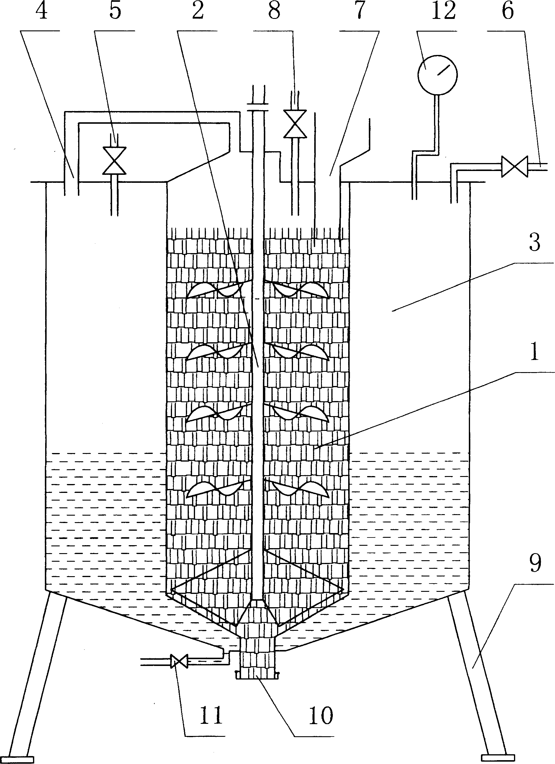
[0017] like figure 1 As shown, there is a biogas generating chamber 1 in the middle, in which a stirrer 2 is installed, and a pressurized chamber 3 is formed on the periphery of the generating chamber 1, and the upper end of the generating chamber 1 and the pressurized chamber 3 are connected through an air guide tube 4 A water inlet pipe 5 is externally connected to the pressurization chamber 3, an air outlet pipe 6 is connected to the upper end of the pressurization chamber 3 and can be connected with a biogas appliance, and a feed inlet 7 and a water pipe 8 are formed on the upper end of the generation chamber 1. The bottom of the pressurization chamber 3 is shaped on a support foot 9, which is movable as a whole. An openable discharge port 10 is formed at the bottom of the generation chamber 1 . A drain valve 11 is installed at the bottom of the boost chamber 3 . The top of the pressurization chamber 3 is also provided with an air pressure indicating gauge 12 .
[0018]...
Embodiment 2
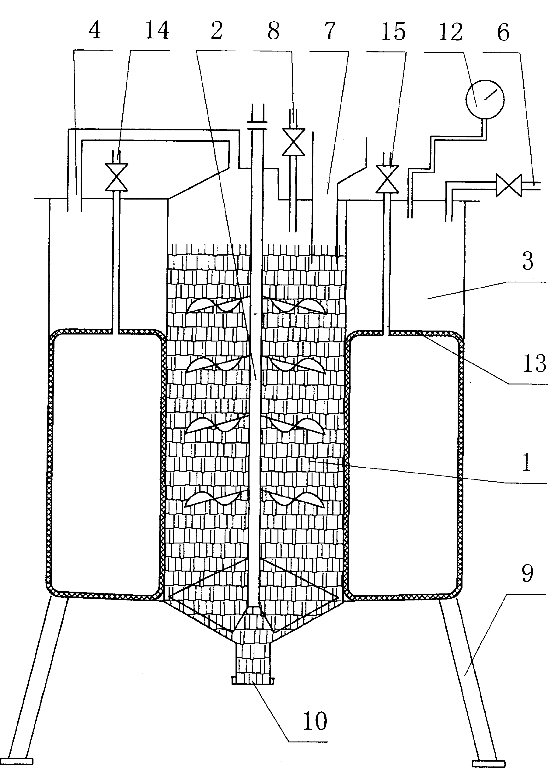
[0020] figure 2 It is a structural principle diagram of a biogas booster generator with a booster chamber equipped with a booster air bag. Compared with embodiment 1, its pressurization mode is that a pressurized air bag 13 is provided in the pressurized chamber 3 , and the intake pipe 14 and the deflation valve 15 communicate with the pressurized air bag 13 . When the air pressure in the pressurization chamber 3 was too low, the air release valve 15 was closed, and the pressurized air bag 13 in the pressurized chamber 3 was inflated by the intake pipe 14, so that the volume of the pressurized air bag 13 was increased, and the air pressure in the pressurized chamber 3 was increased. The biogas pressure increased rapidly. When the biogas is not in use, the air release valve 15 can be opened to remove the air in the pressurized air bag 13, so that the space of the pressurized chamber 3 is increased to store a larger amount of biogas.
Embodiment 3
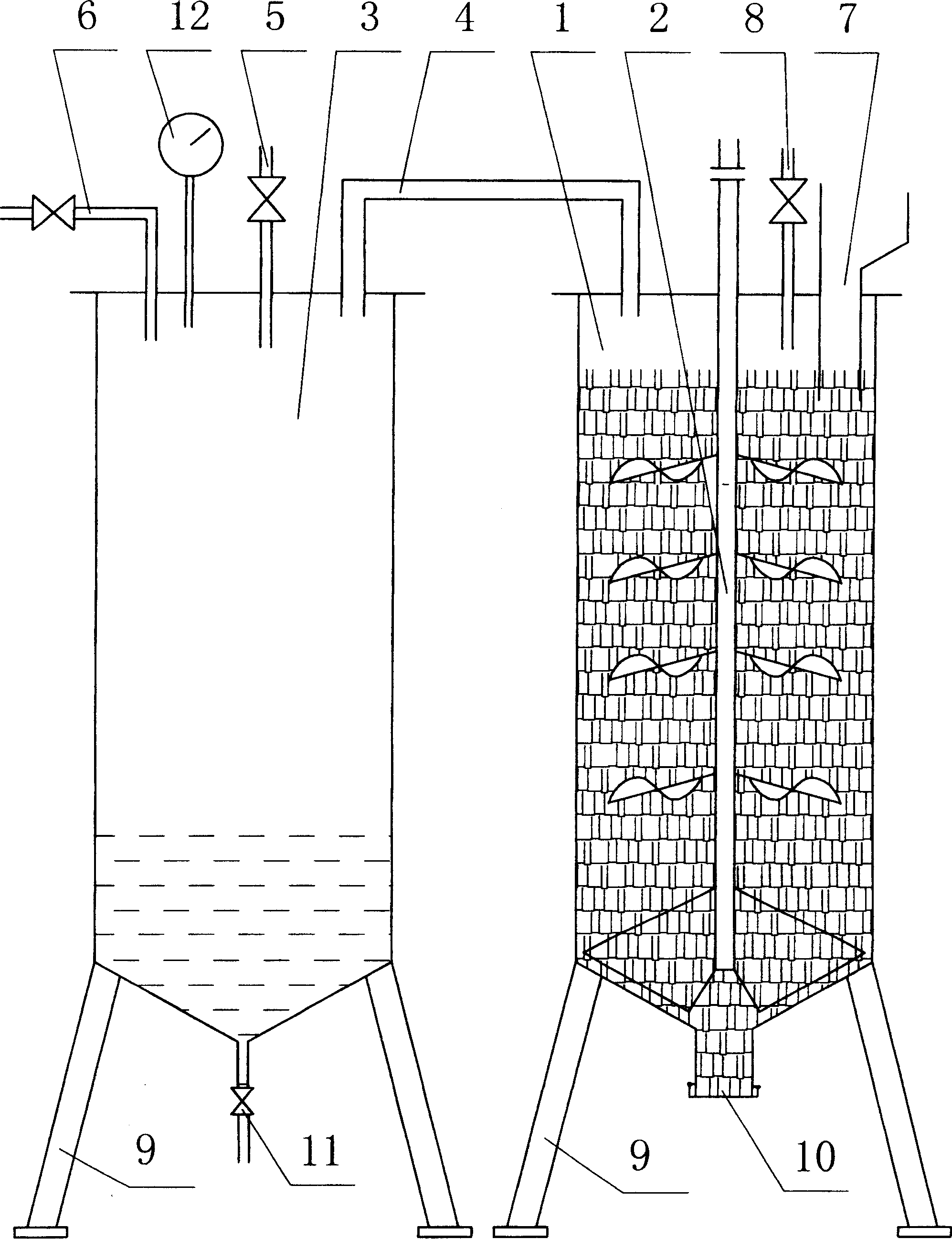
[0022] like image 3 It is a schematic diagram of the structure of a split-type biogas booster generator; compared with Embodiment 1, it is characterized in that the pressurization chamber 3 and the generation chamber 1 are in the form of separate bodies, and the upper ends of the generation chamber 1 and the pressurization chamber 3 pass through the air duct 4 phases are connected. The bottoms of the generating chamber 1 and the pressurizing chamber 3 are respectively shaped with supporting feet 9, which are movable as a whole. All the other make by embodiment 1.
PUM
 Abstract
Description
Claims
Application Information
 - R&D
- Intellectual Property
- Life Sciences
- Materials
- Tech Scout
- Unparalleled Data Quality
- Higher Quality Content
- 60% Fewer Hallucinations
Browse by: Latest US Patents, China's latest patents, Technical Efficacy Thesaurus, Application Domain, Technology Topic, Popular Technical Reports.
© 2025 PatSnap. All rights reserved.Legal|Privacy policy|Modern Slavery Act Transparency Statement|Sitemap|About US| Contact US: help@patsnap.com


