Vacuum freeze drying device

A technology of vacuum freeze-drying and drying chamber, which is applied in the direction of drying solid materials, drying solid materials without heating, drying, etc., which can solve the problems of many materials for production, large external dimensions, and high cost, and achieve low production materials and external dimensions. Small, compact effect

Inactive Publication Date: 2005-10-26
SIFANG TECH GRP CO LTD
View PDF0 Cites 7 Cited by
  • Summary
  • Abstract
  • Description
  • Claims
  • Application Information

AI Technical Summary

Problems solved by technology

[0002] There are two kinds of radial cross-sectional shapes of the drying chamber of the existing vacuum freeze-drying device: one is circular. Although this cylindrical drying chamber has the advantage of less materials for making, the effective utilization rate of the drying interior space is low, and the shape of the cylindrical drying chamber is often low. The size is large, which cannot meet the configuration requirements of a compact vacuum freeze-drying device; the second is rectangular. Although this box-type drying chamber can effectively use the drying room space, the overall size is small, and it can meet the configuration of a compact vacuum freeze-drying device. Requirements, but the drying room must be able to withstand vacuum pressure, more materials are used for production, and the cost is higher

Method used


Image

  • Vacuum freeze drying device
  • Vacuum freeze drying device
  • Vacuum freeze drying device

Examples


Embodiment 1

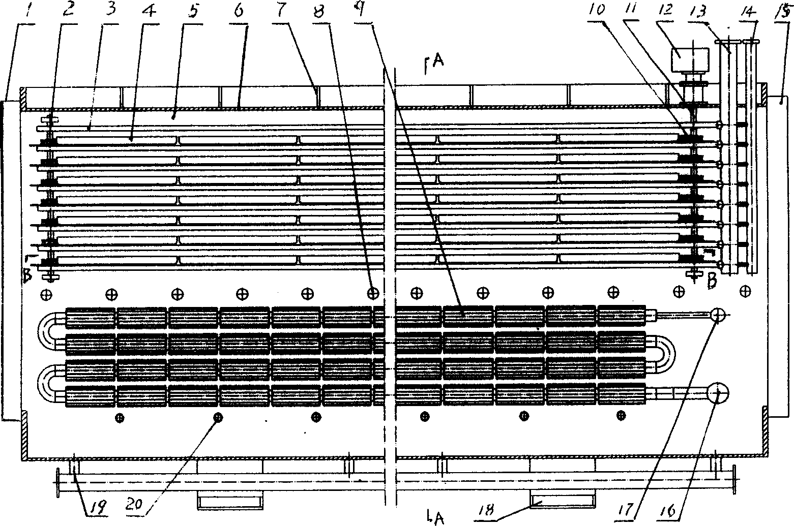
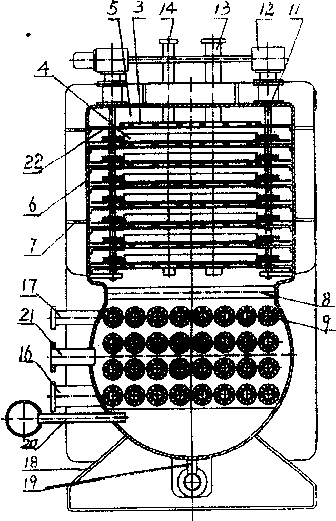
[0013] A kind of vacuum freeze-drying device (see figure 1 , figure 2 ) has a drying chamber 5, supports the heating plate group 3 on the top of the drying chamber with a support 22, communicates with the heating plate group and passes through the heat medium inlet pipe 13 and the heat medium outlet pipe 14 of the drying chamber, and places the trap below the drying chamber. The water evaporator 9, the refrigerant inlet pipe 17 and the refrigerant outlet pipe 16 communicating with the water catcher evaporator and passing through the drying chamber, the vacuum pump connecting pipe 20, the drain pipe 19 and the foot 18 connected with the drying chamber body 6 respectively, the two drying chambers There are airtight doors 1 and 15 at the ends respectively, and the shape of the radial section of the drying chamber is a square or a connection combination of a rectangle and an arc (see figure 2 ), there are load-bearing rods 8 for pressure resistance between the inner sides of th...

Embodiment 2

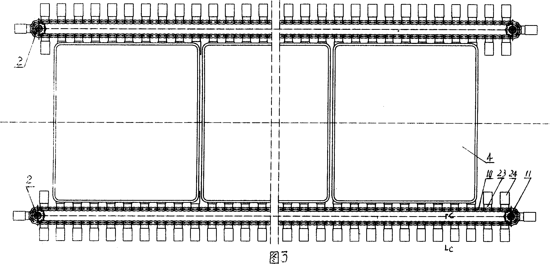
[0016] The difference from Embodiment 1 is that the drying tray 4 is placed on the heating plate 3 (see FIG. 6 ), and the conveying chain, drive motor and sprocket are omitted.

Embodiment 3

[0018] The difference with Embodiment 1 or 2 is: the drying chamber is provided with a drying disc guide rail 25, and the drying disc is placed on the drying disc guide rail 25 (see Figure 5), and the conveying chain, driving motor and sprocket wheel are omitted.


PUM


Abstract

The invention relates to a vacuum freezing and drying device, which comprises the drying chamber, the heating plate group and water-seizing evaporator in the drying chamber, the hot medium input and output tubes connecting the heating plate group and through out of the drying chamber, the cold medium input and output tubes connecting the water-seizing evaporator and through out of the drying chamber, the vacuum pump connecting tube, the draining pipe and the foot separately connecting the drying chamber. One end or two ends of the drying chamber has the sealing door; the radial cross section of the drying chamber is the united composition of square or rectangle and the arc, and the inner sides of the jointing part are connected by the bearing rods. The drying disk is on the heating plate. The strong points of the invention are: meet the collocating demands of the tight vacuum freezing and drying device, the lower cost and the few materials.

Description

Technical field: [0001] The invention relates to a vacuum freeze-drying device. Background technique: [0002] There are two kinds of radial cross-sectional shapes of the drying chamber of the existing vacuum freeze-drying device: one is circular. Although this cylindrical drying chamber has the advantage of less materials for making, the effective utilization rate of the drying interior space is low, and the shape of the cylindrical drying chamber is often low. The size is large, which cannot meet the configuration requirements of a compact vacuum freeze-drying device; the second is rectangular. Although this box-type drying chamber can effectively use the drying room space, the overall size is small, and it can meet the configuration of a compact vacuum freeze-drying device. Requirements, but the drying room must be able to withstand vacuum pressure, more materials are used for production, and the cost is higher. Invention content: [0003] The object of the present inv...

Claims


Application Information

Patent Timeline
Patent Type & Authority Applications(China)
IPC IPC(8): F26B5/06
Inventor 钱洪楼晓华梁惠华
Owner SIFANG TECH GRP CO LTD
Why Eureka
Try Eureka