Symmetrical multiple-slice computed tomography data measuring system

A data measurement and computer technology, applied in the field of diagnostic imaging, can solve the problems of DMS module affecting reliability, limiting the number of scanning speed images, etc., to achieve the effect of reducing quality, reducing spurious noise, and simplifying adjustment

Inactive Publication Date: 2005-10-26
KONINK PHILIPS ELECTRONICS NV
View PDF0 Cites 11 Cited by
  • Summary
  • Abstract
  • Description
  • Claims
  • Application Information

AI Technical Summary

Problems solved by technology

[0013] The weight and segmented structure of the DMS also limits the achievable gantry rotation speed and data throughput, which in turn limits the overall scanning speed and number of images per revolution
The complexity of conventional DMS modules impacts reliability and frequently requires field service by trained personnel for routine maintenance operations such as replacing and readjusting detector array elements

Method used


Image

  • Symmetrical multiple-slice computed tomography data measuring system
  • Symmetrical multiple-slice computed tomography data measuring system
  • Symmetrical multiple-slice computed tomography data measuring system

Examples


Embodiment Construction

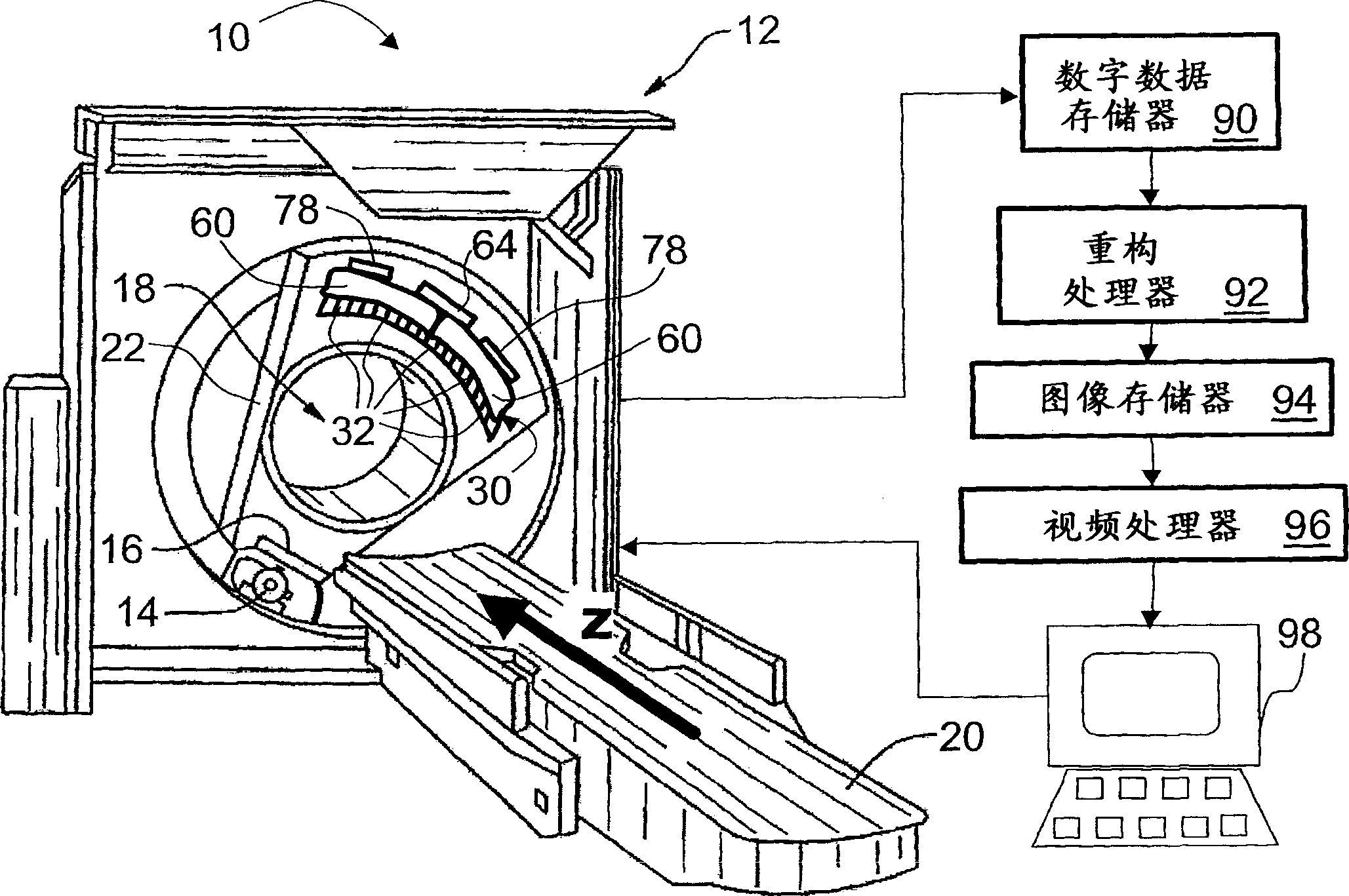
[0038] refer to figure 1 , a computed tomography (CT) imaging apparatus 10 includes a CT scanner 12 including an X-ray source 14 and a collimator 16 coordinated to produce a sector, cone, wedge, Or other shapes of X-ray beams, the examination area 18 contains a patient (not shown), such as a patient on a patient support 20 . The patient support 20 can move linearly along the Z direction, while the X-ray source 14 can rotate on the rotating gantry 22 .

[0039]In a typical helical imaging mode, the gantry 22 rotates to achieve a helical motion of the X-ray source 14 and collimator 16 around the examination region 18 while the patient support 20 is advanced linearly. However, other imaging modalities may also be used, such as single-slice or multi-slice imaging modalities in which the gantry 22 is rotated while the patient support 20 remains stationary, thereby effecting circular movement of the x-ray source 14 to obtain one or more axial images . After completing the axial s...


PUM


Abstract

A data measurement system (DMS) ( 30 ) for a computed tomography (CT) scanner ( 12 ) includes a plurality of connectorized detector sub-array modules ( 32 ). Each detector sub-array module ( 32 ) includes: a scintillator ( 40 ) that produces scintillation events responsive to irradiation by x-rays; a photodetector array ( 42 ) arranged to detect the scintillations; and two symmetrically arranged signal connectors ( 54 1 , 54 2) that transmit the photodetector signals. Symmetrically mounted pipeline cards ( 60 ) mate with the signal connectors ( 54 ) of each side of groups of the detector sub-array modules ( 32 ) to receive the photodetector signals. A processor ( 64 ) communicating with the pipeline cards ( 60 ) receives the photodetector signals from the pipeline cards ( 60 ) and constructs a DMS output from the photodetector signals.

Description

technical field [0001] The present invention relates to diagnostic imaging techniques. In particular, the present invention relates to computed tomography using a two-dimensional detector array capable of rapidly acquiring volumetric imaging data, and will be described in detail. However, the invention is also useful in other types of radiation detectors for various imaging applications using x-rays, visible light, or other types of radiation. The invention is also useful in non-imaging radiation detectors for radiological applications and the like. Background technique [0002] Computed tomography (CT) imaging generally uses an X-ray source that generates a fan-shaped or cone-shaped X-ray beam that passes through the examination region. The patient located in the examination area influences and absorbs part of the passing x-rays. A CT data measurement system (DMS) including a two-dimensional detector array in the cast frame part is arranged opposite the X-ray source to d...

Claims


Application Information

Patent Timeline
Patent Type & Authority Applications(China)
IPC IPC(8): A61B6/03G01T1/164
CPCA61B6/4085G01T1/1647A61B6/027A61B6/032
Inventor M·A·查波R·P·卢塔W·C·布伦内特
Owner KONINK PHILIPS ELECTRONICS NV
Why Eureka
Try Eureka