Exhaust gas recirculation cooler

An exhaust gas recirculation, cooler technology, applied in indirect heat exchangers, heat exchanger types, machines/engines, etc., which can solve problems such as thermal deformation, deterioration of heat exchange rate, etc.

Inactive Publication Date: 2005-10-26
HINO MOTORS LTD +1
View PDF2 Cites 10 Cited by
  • Summary
  • Abstract
  • Description
  • Claims
  • Application Information

AI Technical Summary

Problems solved by technology

[0016] However, in the case of the EGR cooler of the third example, even if a plurality of tubes 33 are arranged in multiple circles at intervals centered on the axis O of the housing 31, the high-temperature exhaust gas 40 flowing from the exhaust gas inlet 37 still has Most of them tend to flow th

Method used


Image

  • Exhaust gas recirculation cooler
  • Exhaust gas recirculation cooler
  • Exhaust gas recirculation cooler

Examples


Example Embodiment

[0042] Hereinafter, embodiments of the present invention will be described based on the drawings.
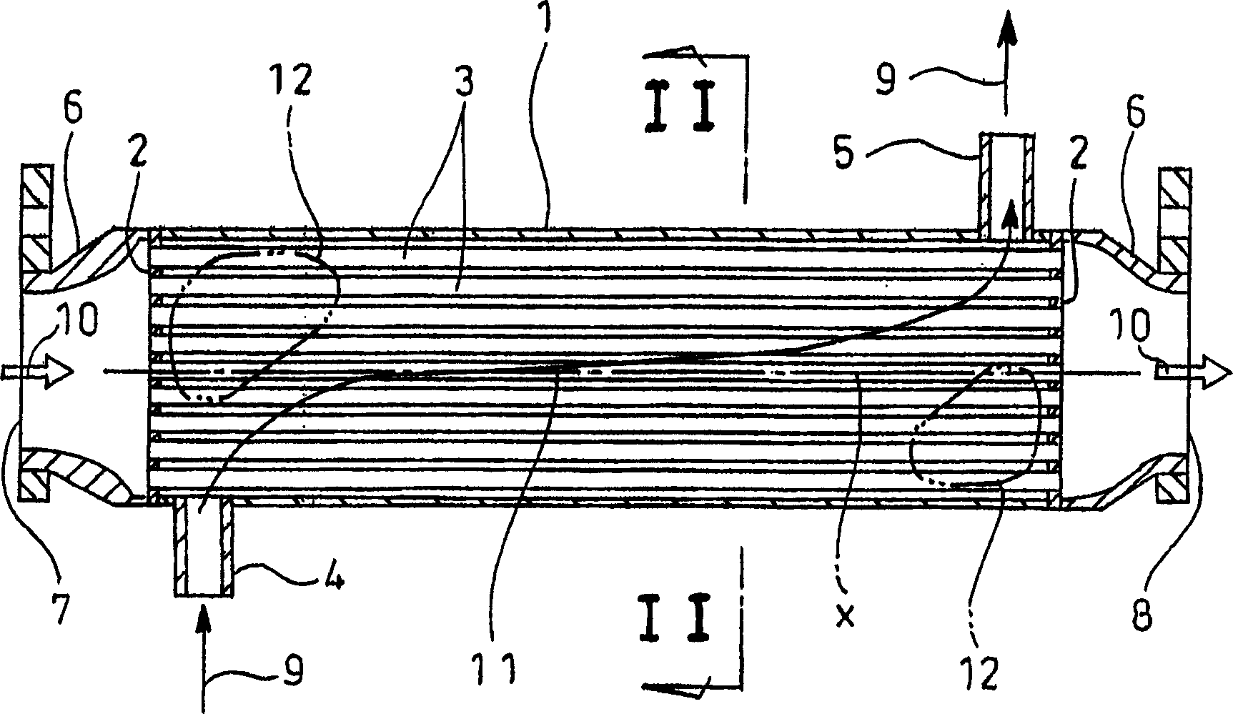
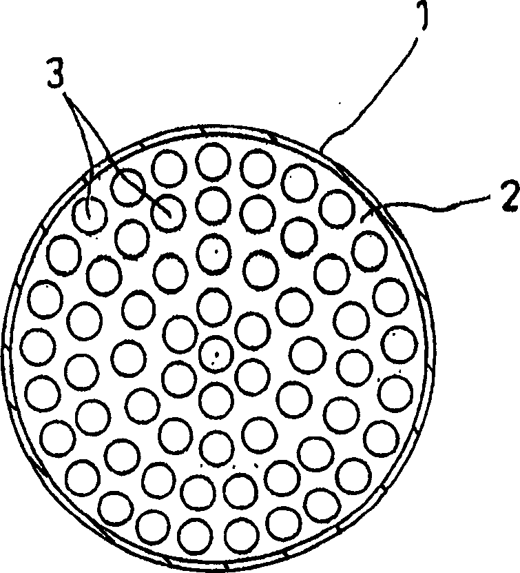
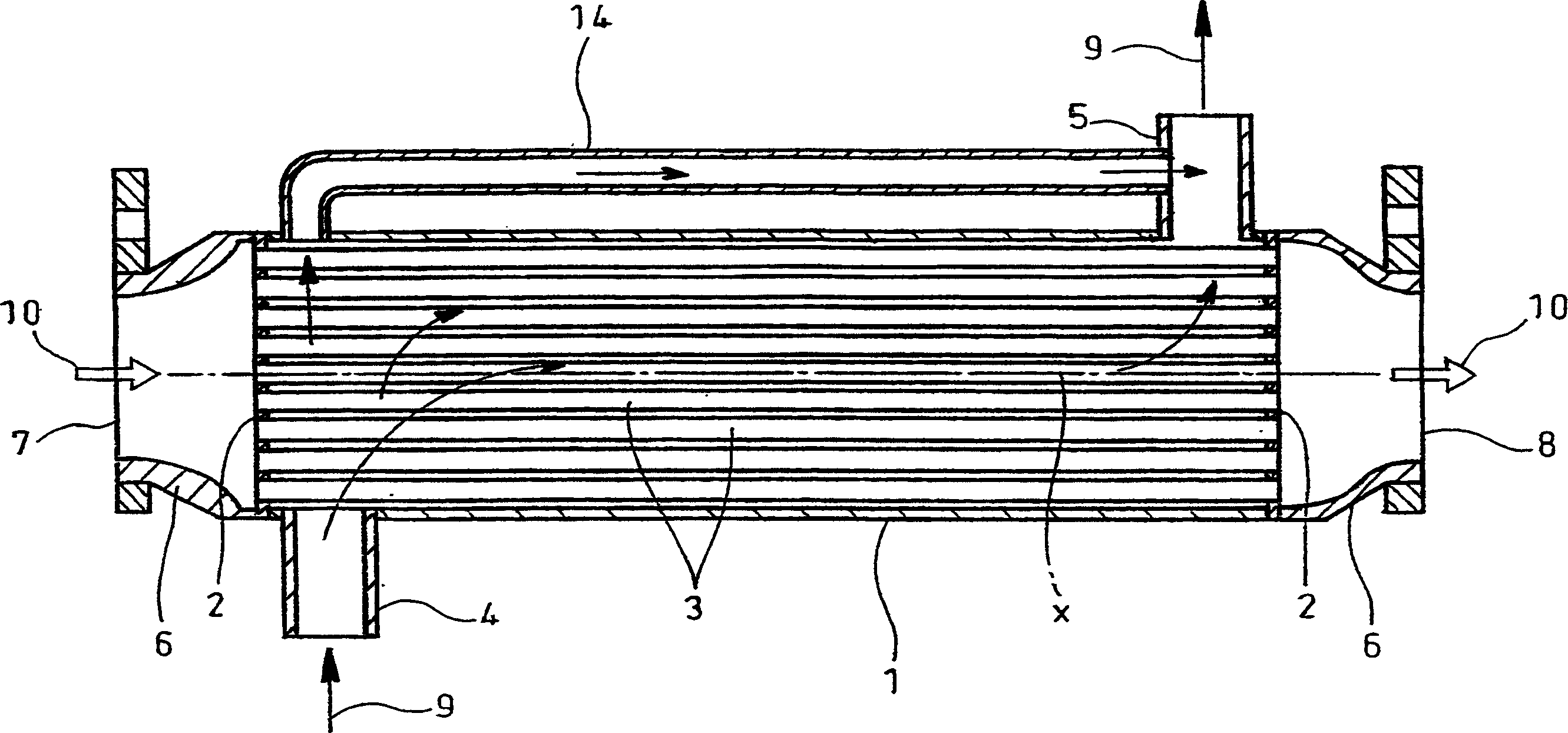
[0043] Figure 6 , Figure 7 Shows the first example of the implementation of the present invention, and Figure 1 ~ Figure 3 The same parts are marked with the same symbols.

[0044] In the EGR cooler of the first example, the number of tubes 3 arranged inside the outer cover 1 is reduced. On the upper side inside the outer cover 1, a predetermined set surrounded by the inner surface 1a, the plates 2, 2 and the tubes 3 of the outer cover 1 is formed In order to form a bypass flow path for the cooling water 9 in a given internal space 15, a bypass pipe 16 composed of one pipe is fixed along the axial direction of the housing 1 by welding, brazing, etc. The method is fixed on the inner side 1a of the outer cover 1.

[0045] The bypass piping 16 forms a bypass inlet 16a at a position opposite to the cooling water inlet 4 in the radial direction of the outer cover 1, and at the same ti...


PUM


Abstract

The invention provides an EGR cooler comprising tubes (3) and a shell (1) enclosing the tubes (3); cooling water (9) is supplied into and discharged from said shell (1); exhaust gas (10) is guided from a diesel engine into the tubes (3) for thermal exchange of the exhaust gas (10) with the cooling water (9). A bypass flow path for guiding the cooling water (9) is constituted within the shell (1) so as to prevent stagnation of the cooling water (9) in the shell (1).

Description

technical field [0001] The invention relates to an exhaust gas of a recirculating diesel engine, attached to an exhaust gas recirculation (EGR) device for reducing the generation of nitrogen oxides, and an EGR cooler for cooling the exhaust gas for recirculation. Background technique [0002] As a conventionally known technology, there is an EGR device that recirculates part of the exhaust gas of an engine such as an automobile and reduces the generation of nitrogen oxides in the engine. However, in such an EGR device, when cooling the exhaust gas recirculated in the engine, in order to By lowering the temperature of this exhaust gas and making its volume smaller, the combustion temperature is lowered and the production of nitrogen oxides is effectively reduced without excessively reducing the engine output. The EGR cooler for exhaust gas is a known technology, such as disclosed in Japanese Patent Application Laid-Open No. 2001-74380. [0003] figure 1 and figure 2 It is...

Claims


Application Information

Patent Timeline
IPC IPC(8): F02M25/07F28D7/16
CPCY02T10/121Y02T10/12
Inventor 杉原启之辻田诚山下洋二三轮直人本间淳司
Owner HINO MOTORS LTD
Why Eureka
Try Eureka