Engine rack structure

An engine bracket and engine technology, which is applied to the substructure, power plant, non-rotational vibration suppression, etc., can solve problems such as cost and weight increase, and achieve the effects of improving workability, suppressing weight or cost increase, and improving positioning accuracy.

Active Publication Date: 2005-11-09
MITSUBISHI MOTORS CORP
View PDF1 Cites 16 Cited by
  • Summary
  • Abstract
  • Description
  • Claims
  • Application Information

AI Technical Summary

Problems solved by technology

However, neither method can directly use existing components, resulting in an increase in cost and weight

Method used


Image

  • Engine rack structure
  • Engine rack structure
  • Engine rack structure

Examples


Embodiment Construction

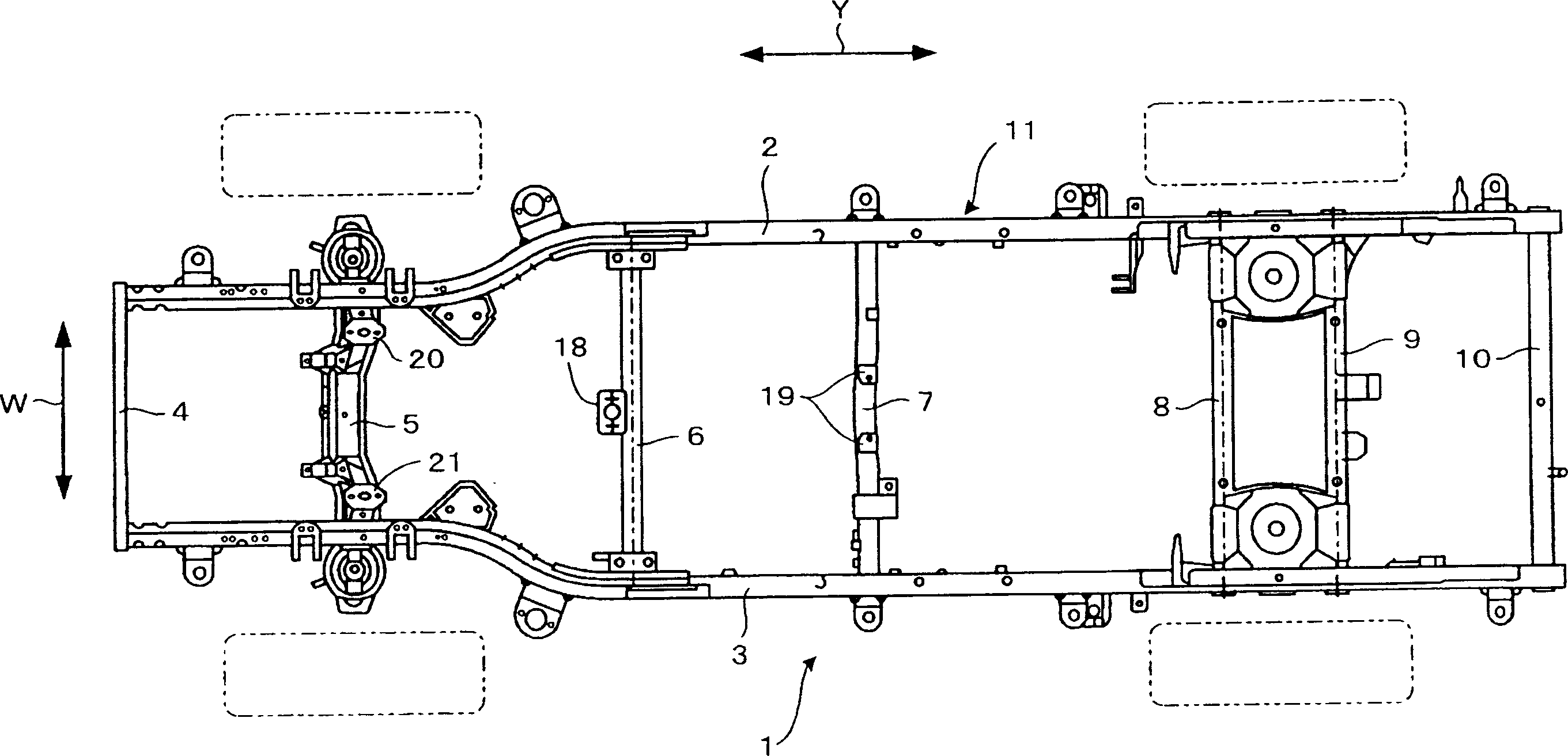
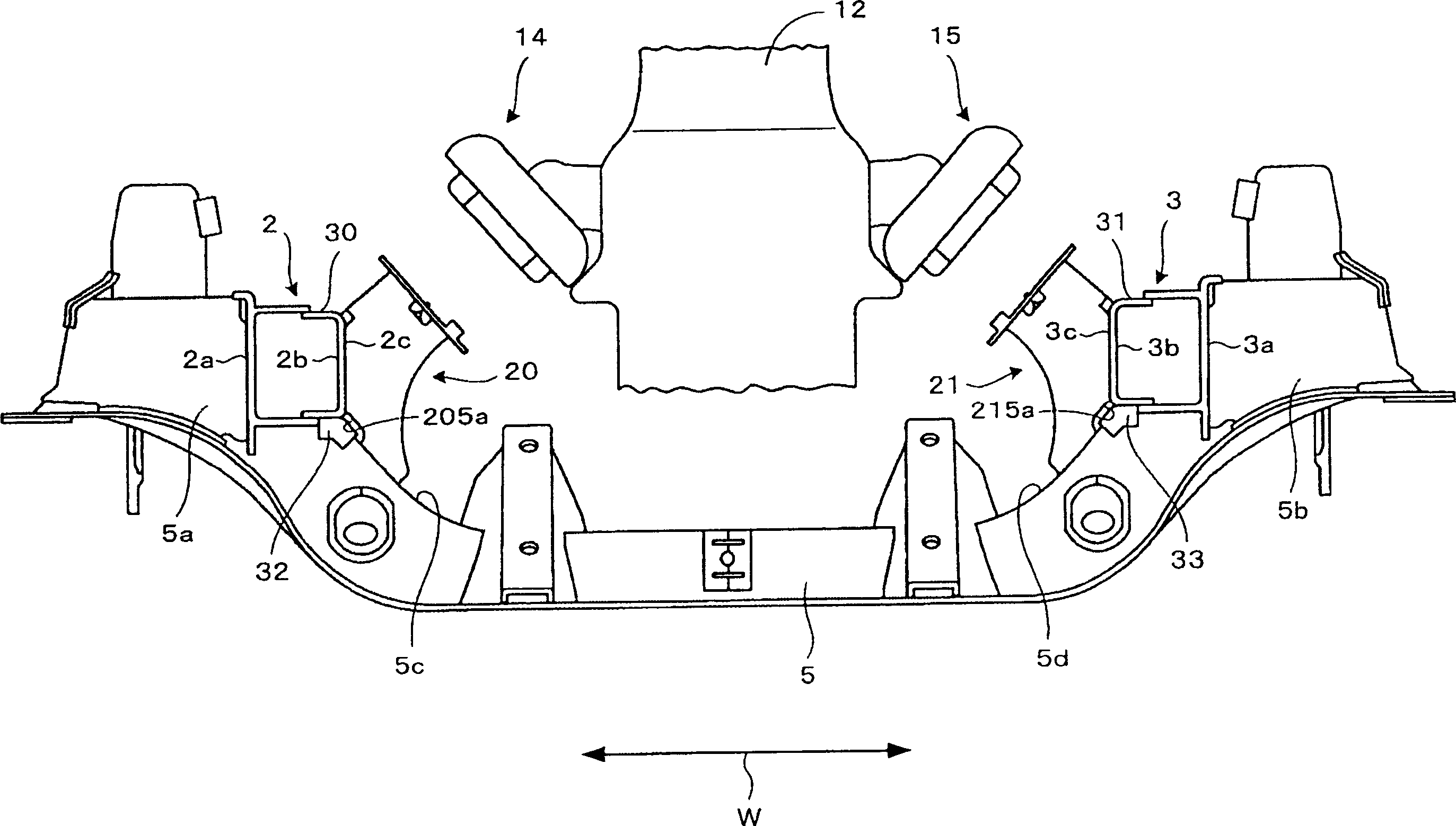
[0018] Embodiments according to the present invention will be described with reference to the drawings. Such as figure 1 As shown, in the vehicle width direction indicated by symbol W, a pair of side members 2 and 3 extending in the front-rear direction of the vehicle 1 indicated by arrow Y are arranged. The vehicle frame 11 is formed by fixing both end sides of the plurality of beams 4 to 10 to the side beams 2 and 3 by welding, respectively. Of these beams, the beam 4 forms the front beam and the beam 10 forms the rear beam. Such as figure 2 As shown, both ends 5a, 5b of the cross member 5 located on the vehicle rear side than the cross member 4 protrude from the side members 2, 3 in the vehicle width direction. A strut portion (not shown) of the front suspension is attached to the protruding both ends 5a, 5b, and functions as a suspension beam. Beams 8 and 9 positioned closer to the front of the vehicle than cross member 10 function as rear suspension beams that suppor...


PUM


Abstract

The invention provides an engine mount structure capable of improving the joint rigidity of a side member and a cross member while suppressing the increase of the weight and cost. The engine mount structure is mounted to an engine 12 arranged between the side members so as to straddle between a pair of side members 2 and 3 that are arranged at an interval in the vehicle width direction W and extend in the longitudinal direction of a vehicle 1 and the cross member 5 of which both end 5a and 5b sides are fixed to respective side members. Engine mount brackets 20 and 21 where engine mount insulators 14 and 15 for elastically supporting the engine are mounted to receiving surfaces 203 and 213 are fixed to the side members 2 and 3 and the cross member 5, and the engine mount insulators 14 and 15 are mounted to receiving surfaces 203 and 213 to support the engine 12.

Description

technical field [0001] The invention relates to a structure of an engine bracket for installing an engine on a vehicle body. Background technique [0002] An engine mount vibration isolator is attached to the engine to elastically hold the engine and absorb vibration when the engine is mounted on the vehicle body. The engine mount vibration isolator is attached to the side of the engine on both sides of the vehicle. The engine mounting bracket, which is the mounting side of the engine mount vibration isolation pad, is generally mounted and fixed to a pair of side beams located in the width direction of the vehicle and constituting the vehicle frame, or to a cross beam whose both ends are fixed to these side beams. on a certain one. For example, Japanese Patent Document 1 describes a structure in which an engine mounting bracket is fixed to a beam. [0003] Japanese Patent Document 1: Patent No. 3006335 [0004] In the engine mount structure shown in Japanese Patent Docume...

Claims


Application Information

Patent Timeline
Patent Type & Authority Applications(China)
IPC IPC(8): B60K5/12B62D21/02F16F15/08
Inventor 樱井宽已
Owner MITSUBISHI MOTORS CORP
Why Eureka
Try Eureka