
Method and device for automatic tracking sun according to time controlled

A technology of tracking the sun and time control, which is applied in the direction of solar thermal devices, heating devices, solar thermal power generation, etc., can solve the problems of unseen practical products, and achieve the effects of compact structure, high tracking accuracy, and reduced floor space

Inactive Publication Date: 2005-11-09
王新庚
View PDF0 Cites 27 Cited by
  • Summary
  • Abstract
  • Description
  • Claims
  • Application Information

AI Technical Summary

Problems solved by technology

However, although there have been various (including by time) inventions of sun tracking devices, practical products have not yet been seen.

Method used


Image

  • Method and device for automatic tracking sun according to time controlled
  • Method and device for automatic tracking sun according to time controlled
  • Method and device for automatic tracking sun according to time controlled

Examples


Embodiment Construction

[0028] As mentioned above, the present invention adopts the technical solution of intermittent operation tracking of mechatronics.

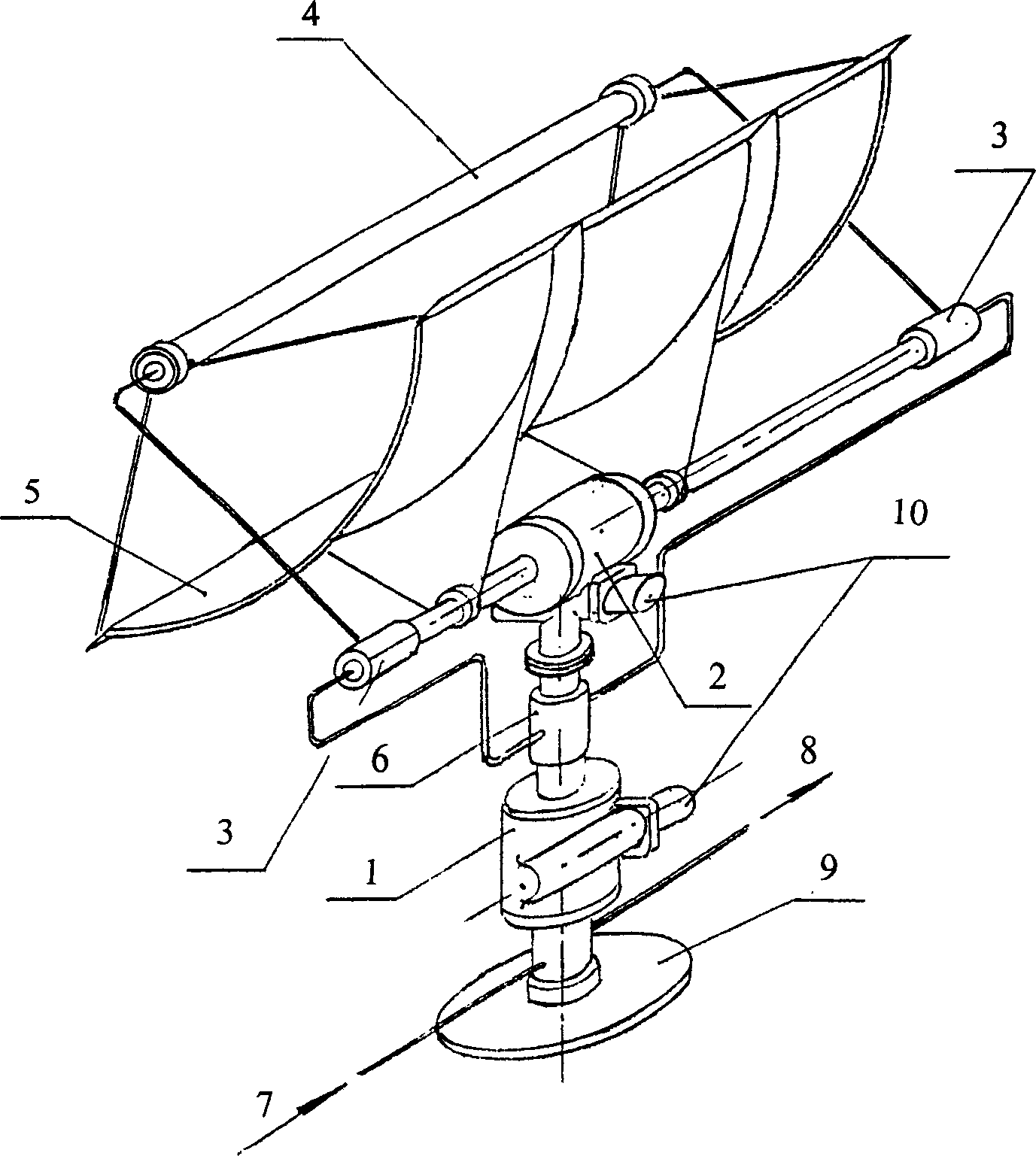
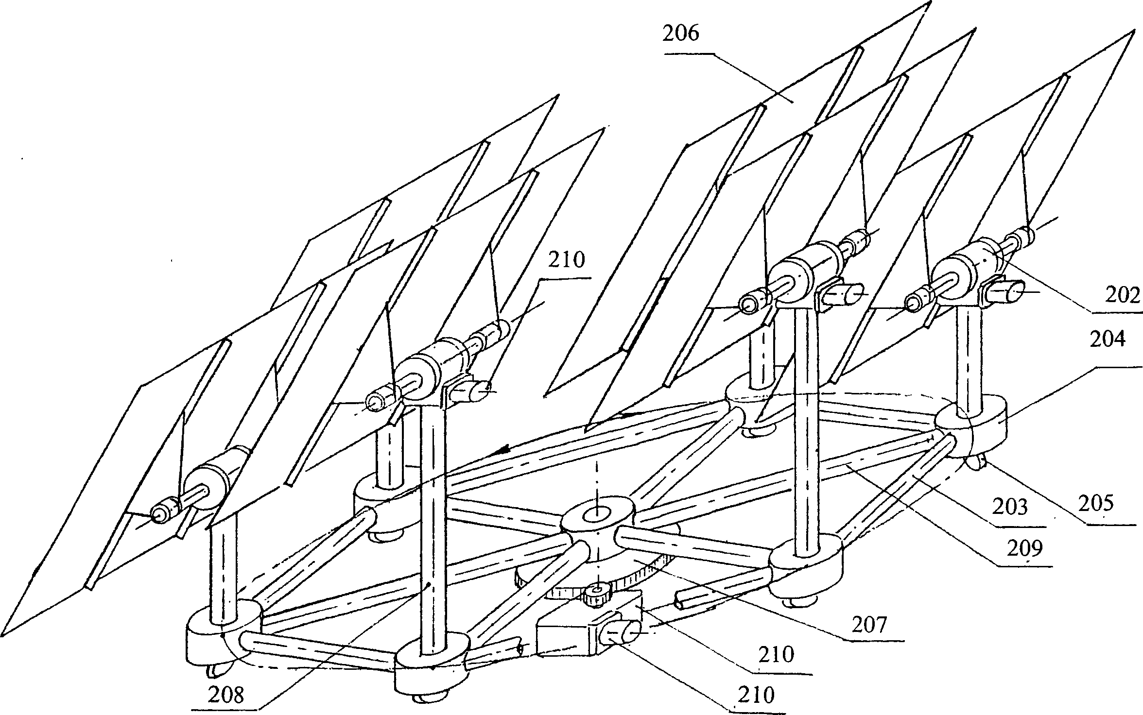
[0029] figure 1 Shown is an example of a monolithic structure for solar heat concentrating, the structure includes a base 9, an azimuth tracking driver 1, an elevation tracking driver 2, a trough parabolic concentrator 5, a vacuum glass tube 4 with a heat pipe, and a The rotary valve 3, rotary valve 6 and other parts are set to solve the problem of hard pipe rotation. The azimuth tracking driver 1 is set on the base 9, and the rotary valve 6 is installed on its output shaft to connect with the elevation tracking driver 2. The output shaft of the elevation tracking driver 2 is connected to the trough parabolic concentrator 5 through a bracket, and is connected to the two sides of the trough parabolic concentrator. Install a rotary valve 3 at each end. The vacuum glass tube 4 with the heat pipe is mounted on the focal point (line) of the trough p...


PUM


Abstract

The invention relates to a method and a device to automatically track sun according to time control. Based on the basic principle of earth running around sun, the real sun time and declination angle would be calculated. Thus, the elevation and the track running time would be calculated from sunrise to sundown, and the relationship of the tracking running of that day and the next day as well. Then, it would return to the location of sunrise when sundown. The track device is made up of elevation track driver and location track driver. The drivers are made up of reducer that use micro deceleration electromotor or step motor as power a Solar energy collector is fixed on the driver by supporting. The electric machine is controlled by computer. The invention is easy to make, low cost, convenience to maintain, and has a broad application range.

Description

[0001] Field of study [0002] The invention relates to a method and a device for tracking the sun according to time control, which can be widely used in the solar energy industry. Background technique [0003] A high-precision, low-cost, fully automatic ideal sun tracking device, the significance of solar energy utilization, is well known to people engaged in the solar energy industry, for example, for photovoltaic power generation, compared with the fixed type, its vertical sunlight. The light-receiving area can be increased by at least 200% in summer, 150% in spring and autumn, and 100% in winter, so the cost of photovoltaic power generation can be greatly reduced. However, although there have been various inventions (including time-based solar tracking devices), practical products have not yet been seen. SUMMARY OF THE INVENTION [0004] In order to overcome the deficiencies of the prior art, the purpose of the present invention is to provide a method for fully automati...

Claims


Application Information

Patent Timeline
Patent Type & Authority Applications(China)
IPC IPC(8): G05D3/00
CPCY02E10/47
Inventor 王新庚
Owner 王新庚
Learn More