

Method for manufacturing parts of multiple way union
A manufacturing method and technology of multi-way pipes, which are applied in the field of manufacturing multi-way metal pipe joints, can solve the problems of increased manufacturing costs of multi-way pipe joints, and achieve the effects of short occupation time, high forming efficiency, and reduced manufacturing costs
- Summary
- Abstract
- Description
- Claims
- Application Information
AI Technical Summary
Problems solved by technology
Method used
Image

Examples
Embodiment Construction
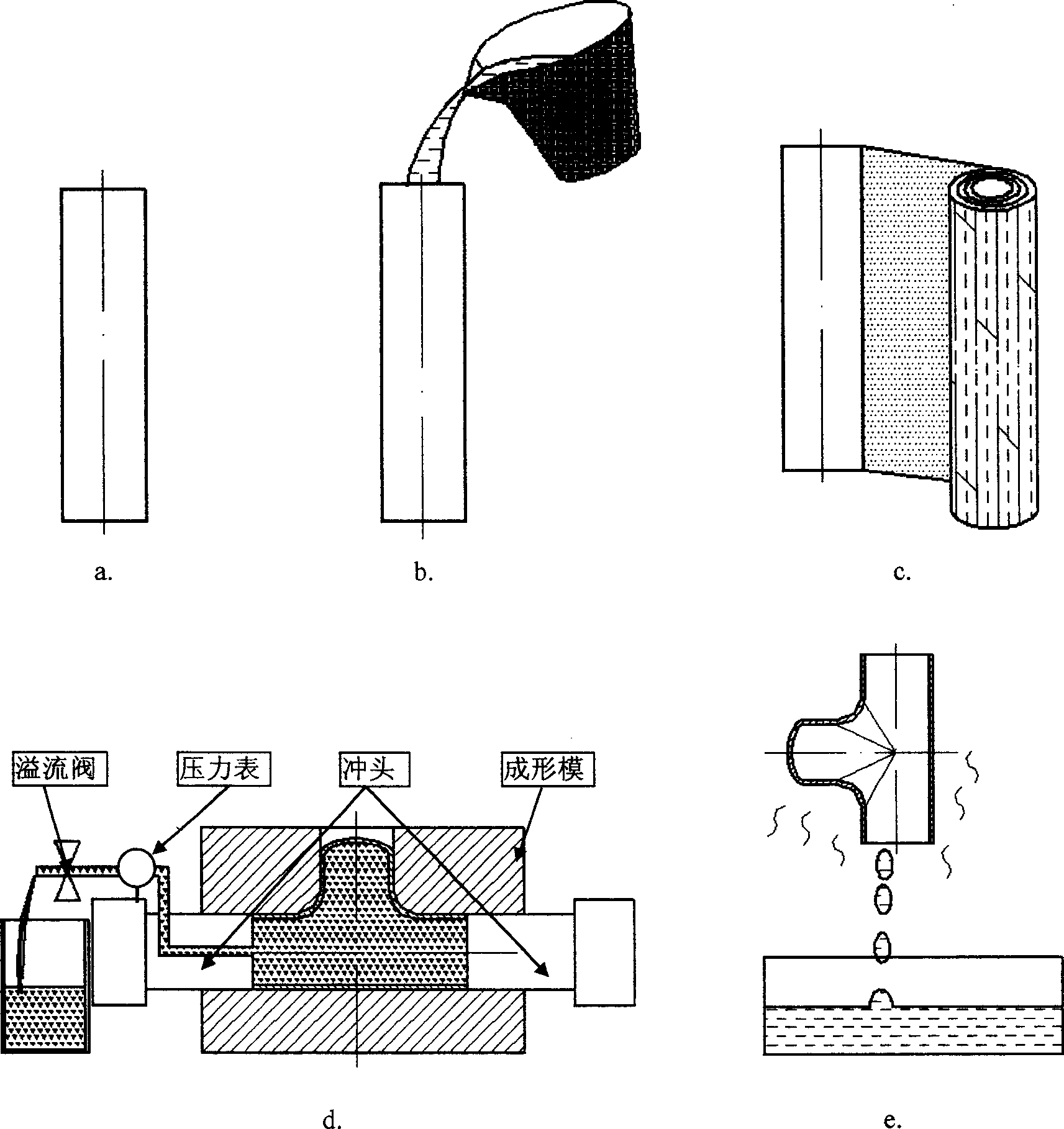
[0014] to combine figure 1 Taking the three-way pipe joint part as an example, describe the concrete manufacturing method of the present invention:
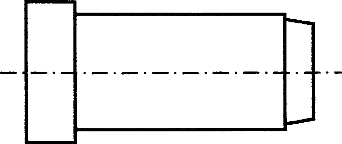
[0015] First cut the straight pipe to length ( figure 1 a), pouring heated and melted low melting point medium such as industrial vaseline into the tube ( figure 1 b); cooled to a solid, the two ends can be sealed with a plastic (such as polyethylene) film with holes in the middle; then wrap the pipe wall with a plastic film (preferably a polytetrafluoroethylene film with a low friction coefficient) ( figure 1 c), into the forming die; at least one of the two punches has a hole in the center. When forming, the punch squeezes the pipe filled with low-melting point medium during the feeding process, which not only feeds the pipe, but also automatically generates internal high pressure by extruding the low-melting point medium, so that the tee part is formed. The tip of the punch has a tapered step ( figure 2 Shown), squeeze in...
PUM
 Abstract
Description
Claims
Application Information