
Method and equipment for measuring torsional vibration of rotating mechanical rotor

A technology of torsional vibration and rotating machinery, which is applied in the directions of measuring devices, rotation vibration suppression, vibration testing, etc. It can solve problems such as poor working conditions, difficult to realize, difficult torsional vibration signal extraction and analysis, etc., and achieves simple installation and high reliability , Improve the effect of measurement accuracy

Inactive Publication Date: 2005-11-16
NORTHWESTERN POLYTECHNICAL UNIV
View PDF0 Cites 24 Cited by
  • Summary
  • Abstract
  • Description
  • Claims
  • Application Information

AI Technical Summary

Problems solved by technology

[0004] In order to overcome the deficiencies in the prior art that the use of torsion strain gauges is difficult to implement due to poor working conditions, and the extraction and analysis of torsional vibration signals is difficult, the present invention proposes a method and device for measuring the torsional vibration of a rotating machinery rotor

Method used


Image

  • Method and equipment for measuring torsional vibration of rotating mechanical rotor
  • Method and equipment for measuring torsional vibration of rotating mechanical rotor
  • Method and equipment for measuring torsional vibration of rotating mechanical rotor

Examples


Embodiment 1

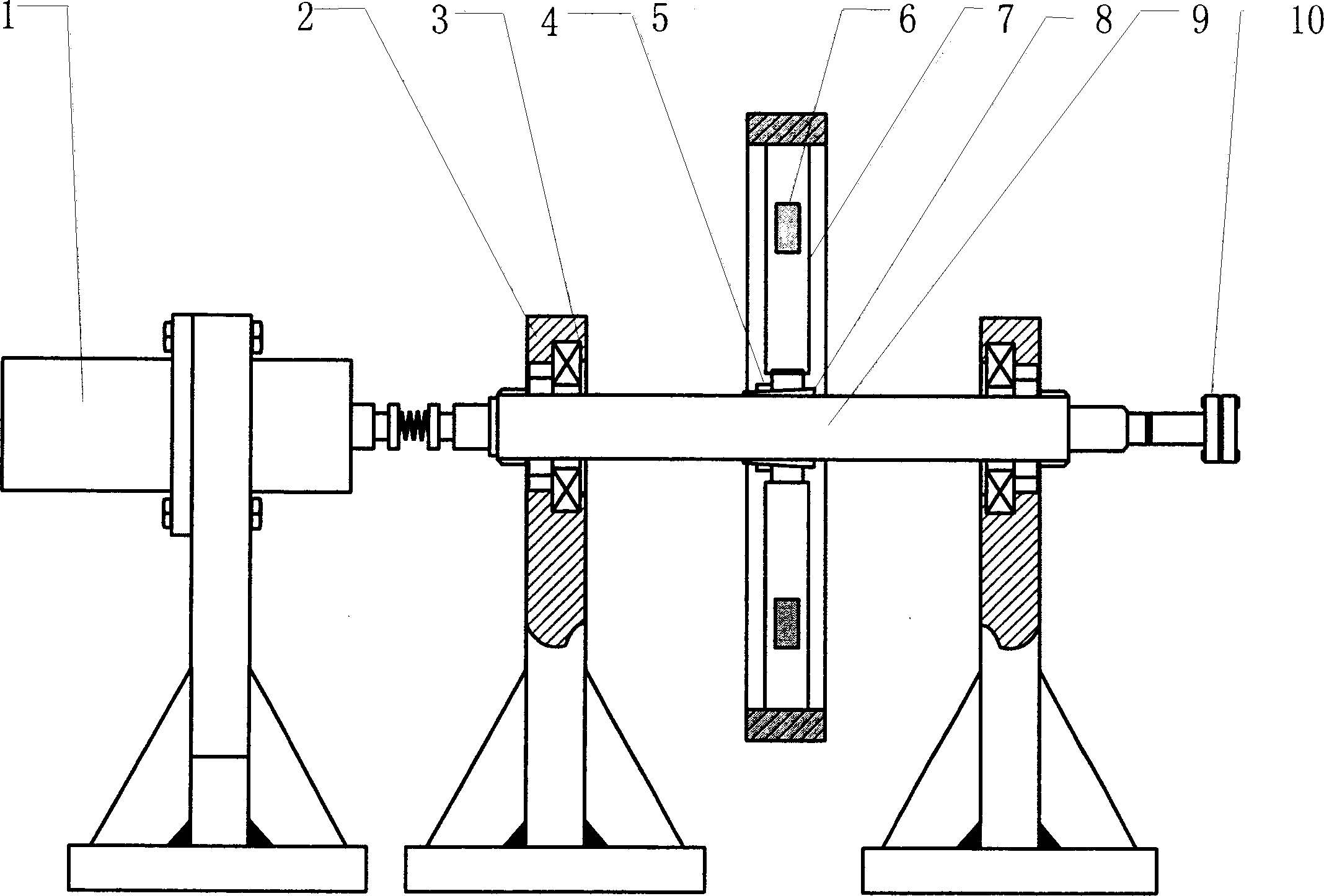
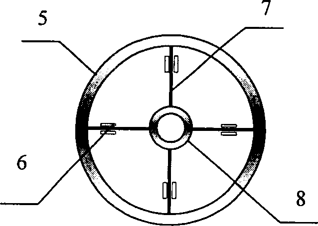
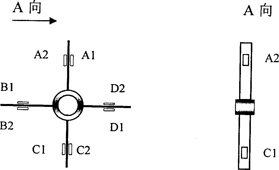
[0023] This embodiment proposes a method for measuring the torsional vibration of a rotary machine rotor and a device for implementing the method.

[0024] The technical solution adopted in this embodiment is to connect a measuring device that moves synchronously with the rotor, and through the elastic sheet 7 on the measuring device, the weak torsional vibration signal generated during the rotor movement is converted into a relatively large amplitude vibration signal. The strain signal is then extracted. Its principle is:

[0025] Let the torsional vibration amplitude of the rotor be = 0 cosΩt( 0 -Amplitude of rotor torsional vibration, Ω-frequency of rotor torsion); inertial ring torsional vibration amplitude is (ω-the natural frequency of the vibration system formed by the inertia ring and 4 elastic pieces, and ω = S I , I-moment of inertia of inertia ring, S-stiffness of ela...

Embodiment 2

[0038] This embodiment proposes a method for measuring the torsional vibration of a rotary machine rotor and a device for implementing the method.

[0039] The technical solution adopted in this embodiment is to connect a measuring device that moves synchronously with the rotor, and through the elastic sheet 7 on the measuring device, the weak torsional vibration signal generated during the rotor movement is converted into a relatively large amplitude vibration signal. The strain signal is then extracted. Its principle is:

[0040] Let the torsional vibration amplitude of the rotor be = 0 cosΩt( 0 -Amplitude of rotor torsional vibration, Ω-frequency of rotor torsion); inertial ring torsional vibration amplitude is (ω-the natural frequency of the vibration system formed by the inertia ring and 4 elastic pieces, and ω = S I , I-moment of inertia of inertia ring, S-stiffness of ela...


PUM


Abstract

A method for measuring torsional vibration of rotary mechanical rotator includes setting torsional vibration measuring unit with the same rotating speed as tested rotator on the tested rotator, using elastic plate on said unit to convert weak torsional vibration signal to be active strain signal in quite large amplitude to increase S - N ratio for obtaining original torsional vibration signal through extraction and analysis. The device for realizing the method comprises a strainmeter pair formed by two strainmeters on each pair of elastic plate and independent signal loop formed by switching in Wheatstone bridge.

Description

(1) Technical field: [0001] The invention relates to a method and a device for measuring the torsional vibration of a rotary machine rotor. (2) Technical background: [0002] In the field of state monitoring and fault diagnosis of rotating machinery, with the emergence of large power grids, the threat of torsional shock to the stability and safety of the rotor shafting has become more prominent. Therefore, the measurement of torsional vibration of the shafting is an important An important link in condition monitoring and fault diagnosis of rotating machinery. But until now, the measurement of torsional vibration has been difficult. [0003] In November 2003, the digital journal "Foreign Electronic Components" introduced a torsional vibration measurement method in the article "JN338 Intelligent Digital Torque Speed ​​Sensor and Its Application". In this method, the torsion strain gauge is directly installed on the shaft, and the torsion strain gauge is used as a sensitive e...

Claims


Application Information

Patent Timeline
IPC IPC(8): G01M7/02
Inventor 廖明夫段曙光
Owner NORTHWESTERN POLYTECHNICAL UNIV
Learn More