Method for fabricating guiding light plate frame

A manufacturing method and technology for a light guide plate, applied in optics, nonlinear optics, instruments, etc., can solve the problems of light gathering and insufficient assembly strength, and achieve the effect of strong bonding force and solving the reduction of assembly strength.

Inactive Publication Date: 2005-11-16
TPO DISPLAY
View PDF0 Cites 8 Cited by
  • Summary
  • Abstract
  • Description
  • Claims
  • Application Information

AI Technical Summary

Problems solved by technology

[0007] Therefore, the object of the present invention is to provide a method for manufacturing a light guide plate and a frame, so as to solve the problem of insufficient assembly strength of the known technology due to the thinning of the light guide plate and fr...

Method used


Image

  • Method for fabricating guiding light plate frame
  • Method for fabricating guiding light plate frame
  • Method for fabricating guiding light plate frame

Examples


no. 1 example

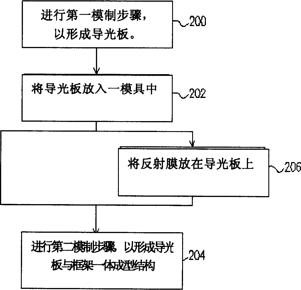
[0035] Such as figure 2 Shown is a manufacturing flow chart of the light guide plate and the frame in the backlight module according to a preferred embodiment of the present invention.

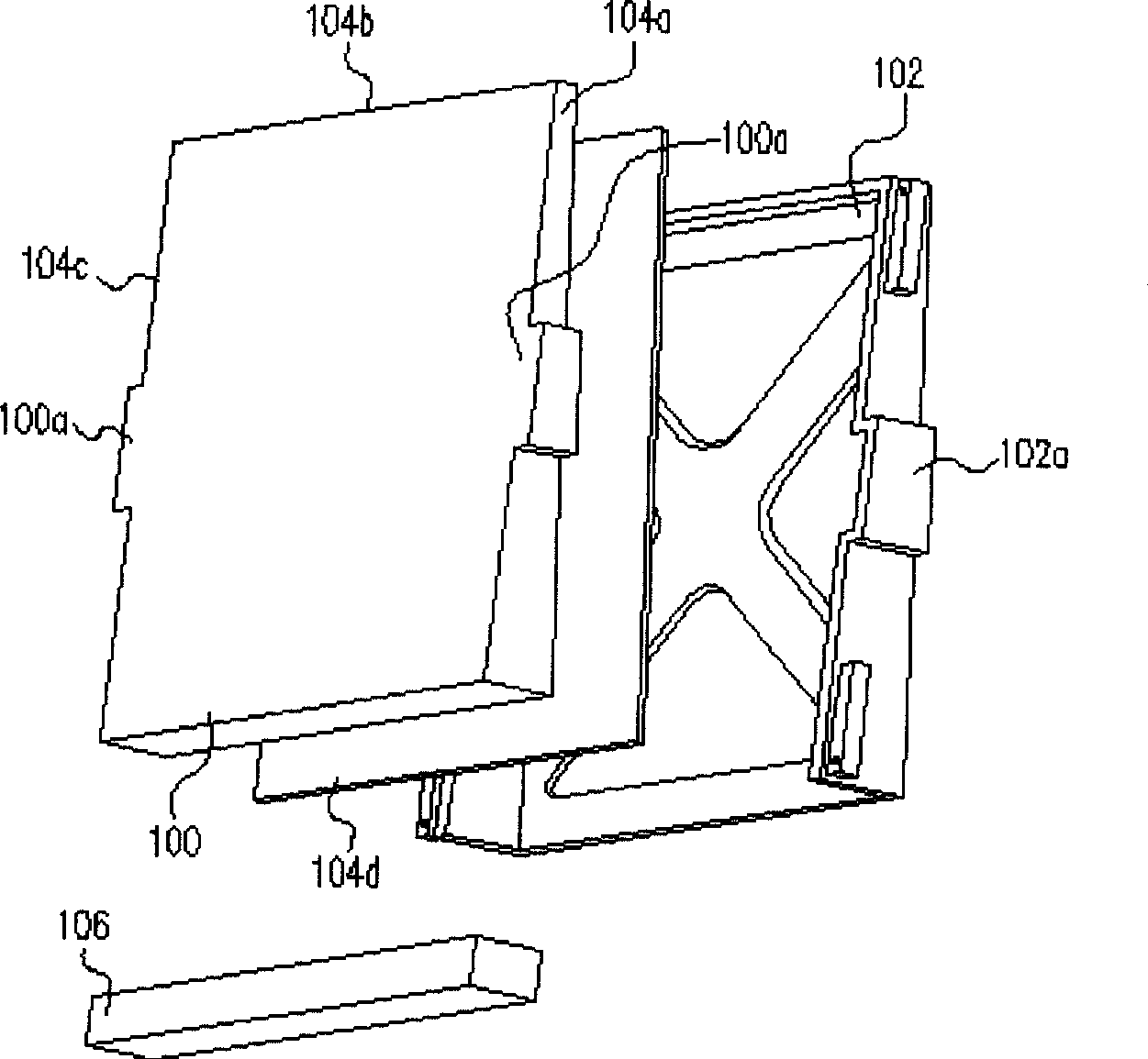
[0036] Please refer to figure 2 , first perform a first molding step (such as an injection molding step or an injection molding step) to form a light guide plate (step 200), the formed light guide plate is as Figure 4 As shown, the light guide plate 400 is a wedge-shaped light guide plate, and its material can be a transparent plastic material. It is particularly worth mentioning that the side surfaces 408, 412 of the light guide plate 400 of the present invention do not need to be designed with protrusions for assembling and combining with the frame, so the sides of the light guide plate 400 of the present invention are flat planes. The problem of easy to gather light will not happen due to the unique design.

[0037] Afterwards, the light guide plate is put into a mold (step 202 ), whe...

no. 2 example

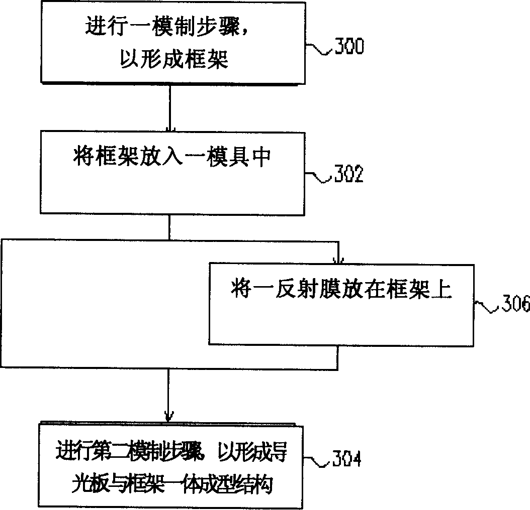
[0042] Such as image 3 Shown is a manufacturing flow chart of the light guide plate and the frame in the backlight module according to another preferred embodiment of the present invention.

[0043] Please refer to image 3 , first perform a first molding step (such as an injection molding step or an injection molding step) to form the frame (step 300), wherein in one embodiment, the material used in the first molding step can be It is a reflective material, so that the formed frame has reflective properties, and the formed frame has its specific frame shape according to the design, such as Figure 6 shown.

[0044] Afterwards, the frame is put into a mold (step 302), wherein the bottom surface of the frame is flat against the bottom of the mold. Then perform a second molding step (for example, an injection molding step or an injection molding step) to form an integrally formed structure of the light guide plate and the frame (step 304), and the formed integrally formed stru...


PUM


Abstract

A method for preparing light guide plate and frame includes moulding light guide plate and then integrating moulded light guide plate with frame to form one body structure or moulding frame and then integrating moulded frame with light guide plate to form one body structure. The frame is prepared to be light reflecting type.

Description

technical field [0001] The present invention relates to a method for manufacturing a backlight module of a liquid crystal display (Liquid Crustal Display, LCD), and in particular to a backlight module (Back-Light Module) in which a light guide plate (Light Guide Plate) and a frame (Mold Frame) are combined into a Integrated manufacturing method. Background technique [0002] In recent years, with the development of liquid crystal displays, the combination with electronic components has become more widely used, and the functions have become more complete. However, the production of relatively liquid crystal displays has become more and more complicated. Generally speaking, liquid crystal displays can be divided into three types: reflective liquid crystal displays, transmissive liquid crystal displays, or semi-reflective and semi-transmissive liquid crystal displays. Usually, in the transmissive liquid crystal display and semi-reflective semi-transmissive liquid crystal displ...

Claims


Application Information

Patent Timeline
IPC IPC(8): G02F1/1335
Inventor 陈英杰庄孟儒
Owner TPO DISPLAY
Why Eureka
Try Eureka