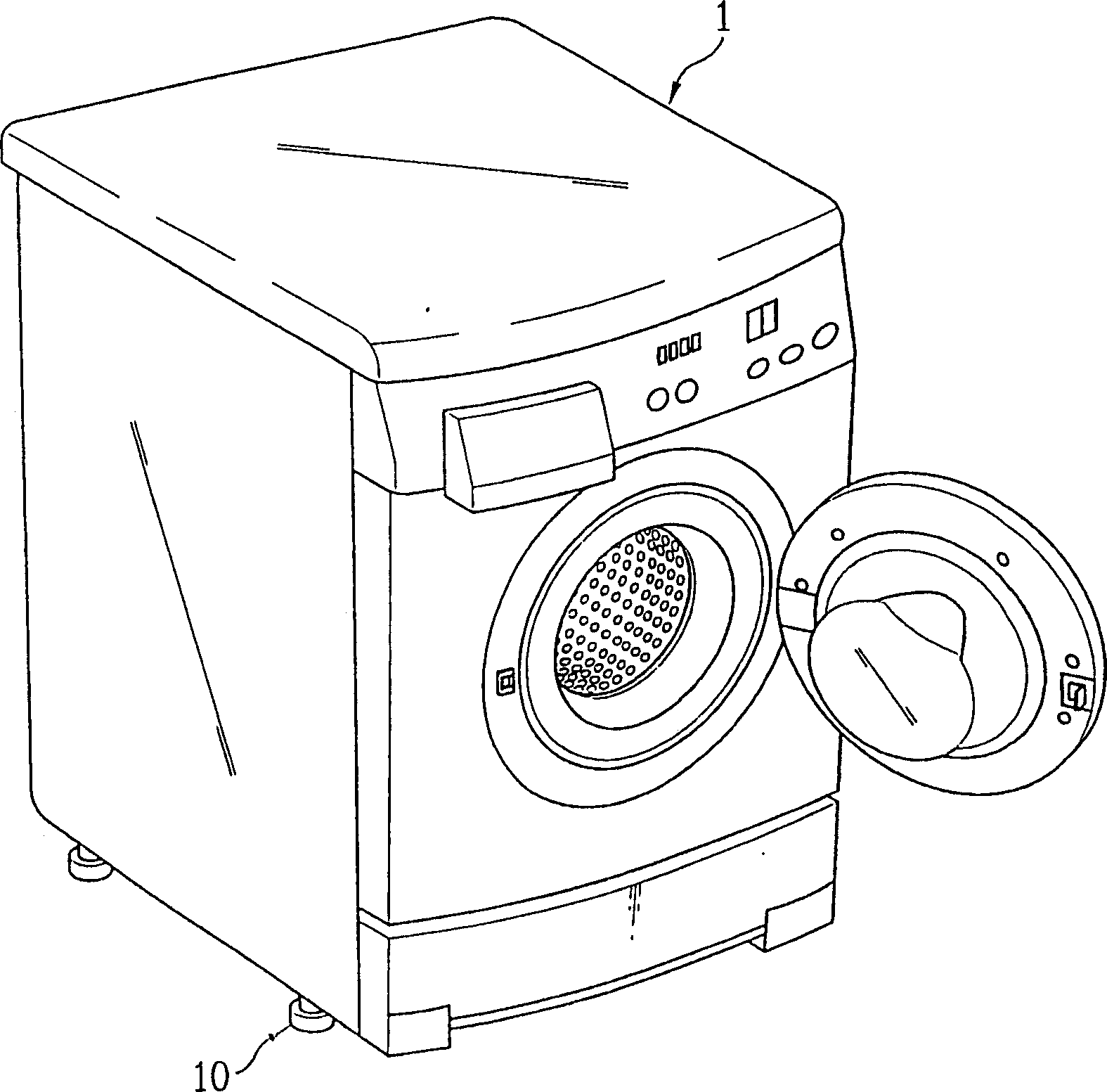
Leg assembly for home appliance
A technology for household appliances and feet, which is applied in the field of foot components, and can solve problems such as complicated processes, low work efficiency of workers, and reduced aesthetics of feet 10
- Summary
- Abstract
- Description
- Claims
- Application Information
AI Technical Summary
Problems solved by technology
Method used
Image

Examples
no. 1 example
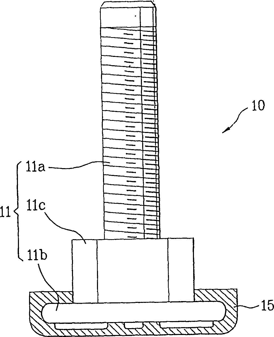
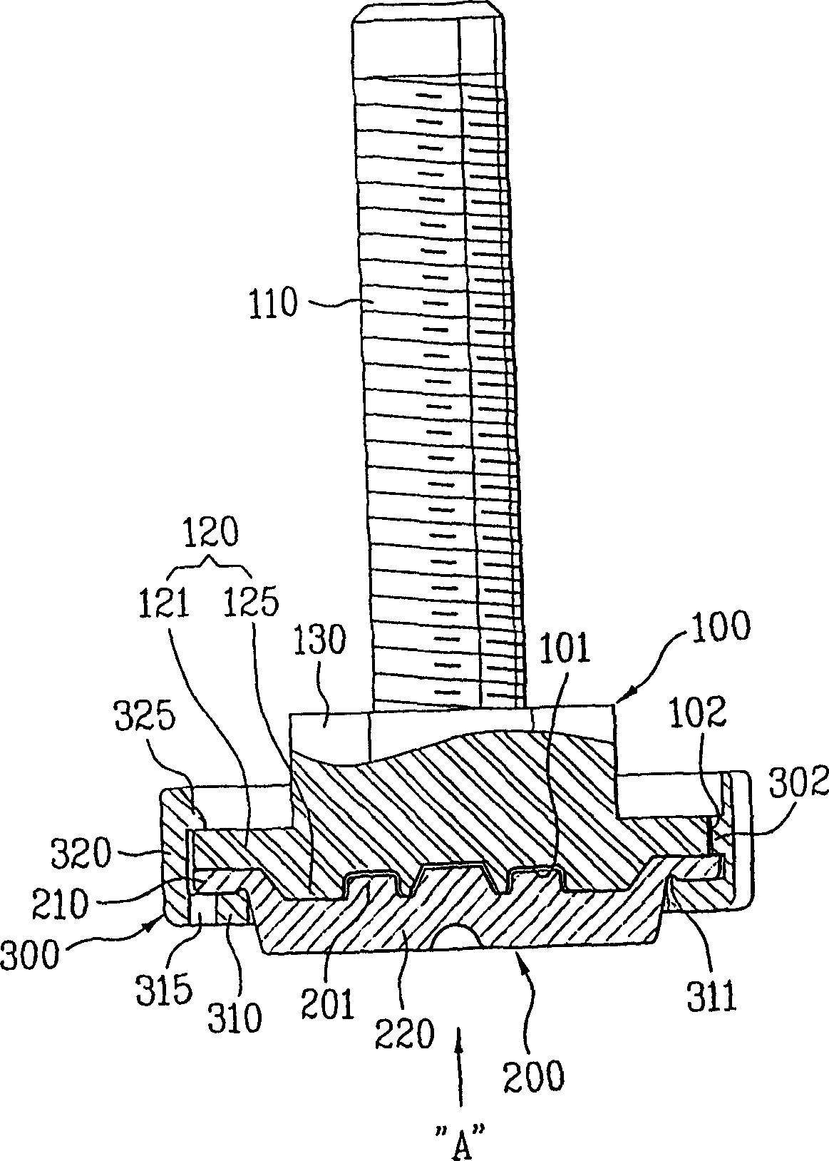
[0049] Foot bolts 100 are connected to household appliances (not shown), such as image 3 , 50, and 6A, the foot bolt includes a long screw 110 and a head 120.
[0050] In this case, the screw rod 110 is connected to the lower edge of the household appliance, so that the height of the foot bolt 100 can be adjusted by rotating the screw rod 110 .
[0051] A head 200 is provided at the end of the screw 110 , the head includes a flat head 121 and a platform 125 . In this case, the flat head 121 is shaped like a disk, and the platform 125 protrudes from the flat head 121 in a direction opposite to the advancing direction of the screw 110 .
[0052] In addition, a head 130 is further included between the head 120 and the screw 110 . Such as Figure 6A As shown, the angled head 130 includes an angled outer perimeter. Therefore, when setting the angled head, a worker can easily rotate the foot bolt 100 by using a tool such as a wrench or a wrench.
[0053] Meanwhile, the pad 200...
no. 2 example
[0087] Such as Figure 7 As shown, the foot assembly according to the second embodiment of the present invention includes a foot bolt 100, a pad 200, and a fixing member 300 having an inner fixing member 300a and an outer fixing member 300b. In this case, the structure of the foot bolt 100 and the pad 200 is the same as Figure 6A and Figure 6B The structure shown in is the same. and Figure 6A and Figure 6B The structure of the illustrated foot bolt 100 and pad 200 has been described in sufficient detail in the description of the first embodiment of the present invention.
[0088] Therefore, the description of the foot bolt 100 and the pad will be omitted, and only the fixing member 300 including the inner fixing member 300a and the outer fixing member 300b will be described below. For reference, for the foot bolt 100 and the pad 200, the same reference numerals as those used in the first embodiment of the present invention will be used.
[0089] Contrary to the fact ...
PUM
 Abstract
Description
Claims
Application Information
 - R&D
- Intellectual Property
- Life Sciences
- Materials
- Tech Scout
- Unparalleled Data Quality
- Higher Quality Content
- 60% Fewer Hallucinations
Browse by: Latest US Patents, China's latest patents, Technical Efficacy Thesaurus, Application Domain, Technology Topic, Popular Technical Reports.
© 2025 PatSnap. All rights reserved.Legal|Privacy policy|Modern Slavery Act Transparency Statement|Sitemap|About US| Contact US: help@patsnap.com