
Baseband multi-path fading channel simulator

A multipath fading channel and multipath fading technology, applied in transmission monitoring, electrical components, transmission systems, etc., can solve the problems of consuming a large number of triggers and high sampling rate, achieve convenient upsampling multiples, reduce useful signal distortion, high precision effect

Inactive Publication Date: 2005-11-30
TSINGHUA UNIV
View PDF0 Cites 19 Cited by
  • Summary
  • Abstract
  • Description
  • Claims
  • Application Information

AI Technical Summary

Problems solved by technology

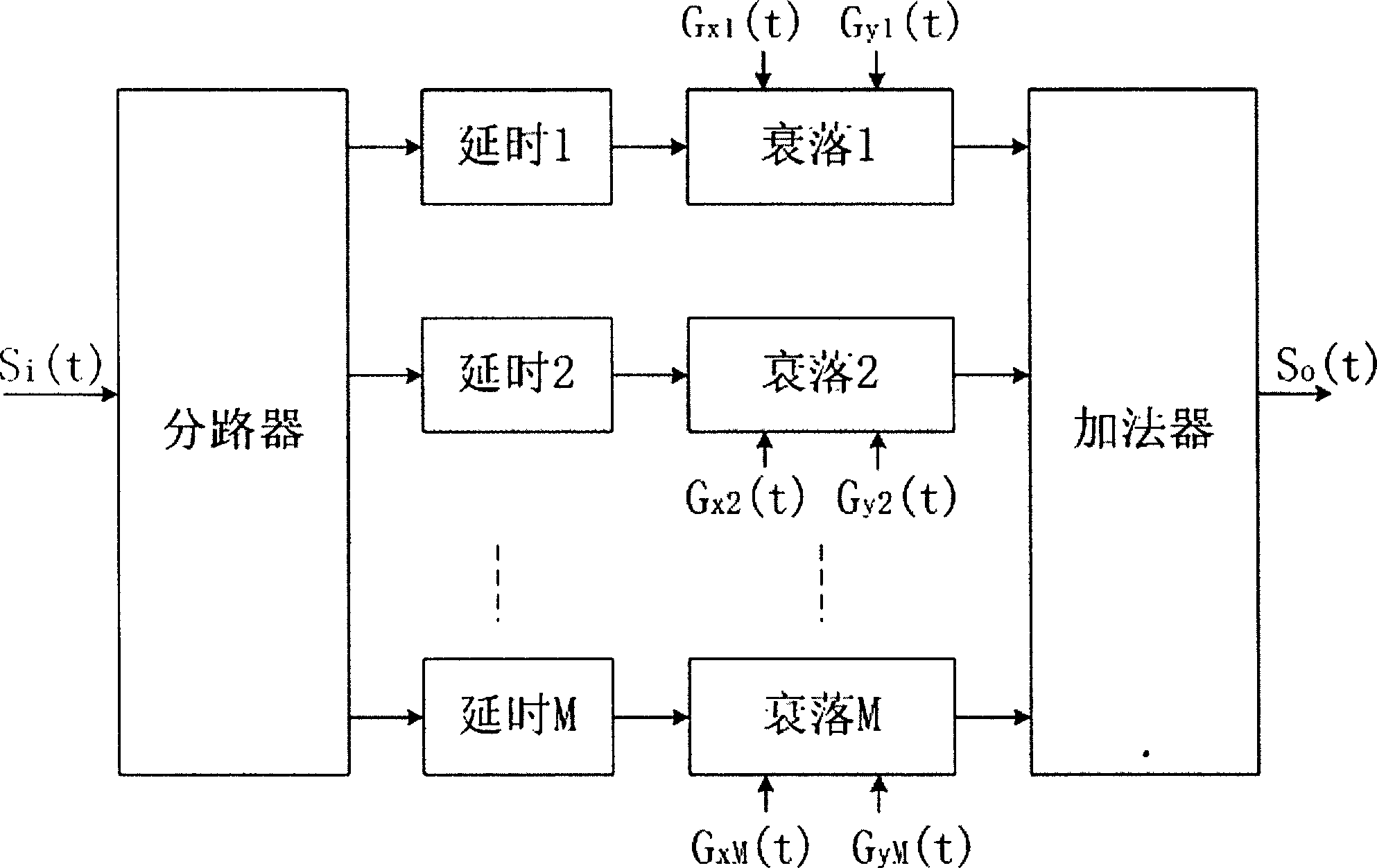
When generating multipath fading signals, it is necessary to delay each path according to the delay amount in a given channel model, and because the sampling rate of broadband wireless systems is high, to simulate channels with long delays (such as digital TV broadcasting) SFN channel in ), it needs to consume a large number of flip-flops or memory resources

Method used


Image

  • Baseband multi-path fading channel simulator
  • Baseband multi-path fading channel simulator
  • Baseband multi-path fading channel simulator

Examples


specific Embodiment approach

[0051] [Symbol Description]

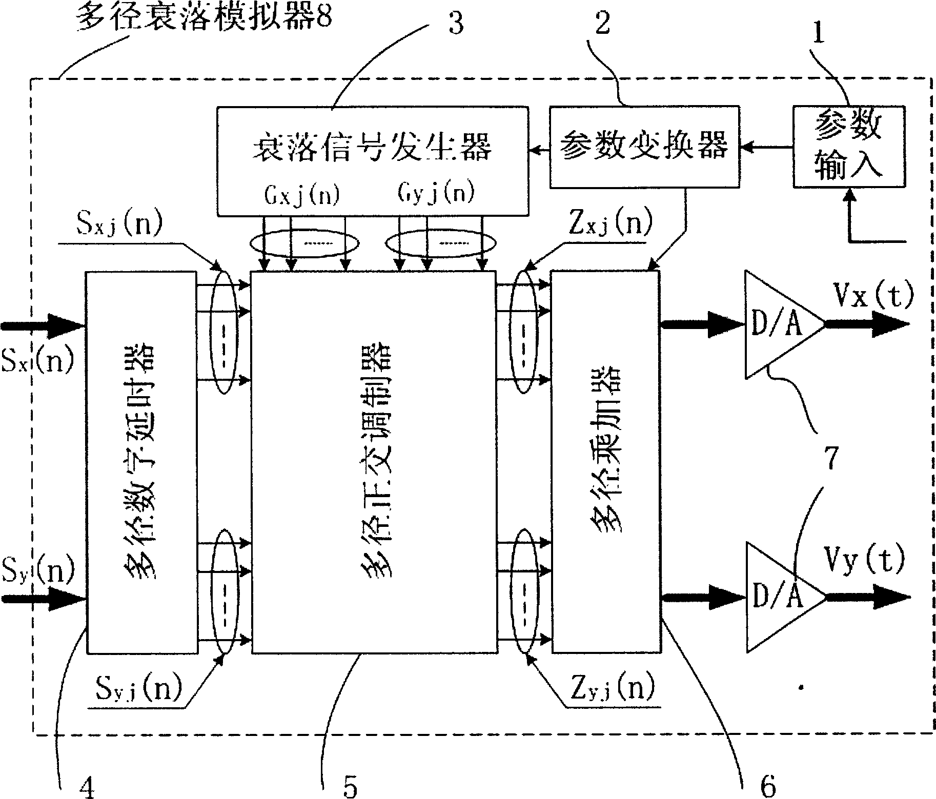
[0052] 1 parameter input; 2 parameter converter; 3 fading signal generator; 4 multipath digital delayer; 5 multipath quadrature modulator; 6 multipath multiplier adder; 7 digital-to-analog converter; 9 data pre-generation unit; 10 storage unit; 11 time division multiplexer; 12 frequency controller group; 13 dual-port RAM group; 14 counter group; 15 multiplexer group.

[0053] Embodiments of the present invention will be described below with reference to the drawings.

[0054] image 3 is the multipath fading channel simulator proposed by the present invention. It is implemented directly at baseband with no frequency shifting blocks at its input. In the verification of wireless systems, its position as Figure 4 As shown, it is located before the I / Q modulator. The multipath fading channel simulator 8 proposed by the present invention is made of the following components: parameter input unit 1, parameter converter 2, fading signal generator 3,...


PUM


Abstract

This invention relates to analogue wireless multi-path declining signal device, which is characterized by the following: the declining signal generation is based on multi-sampling signal process structure and it reads the declining signals through Doppler frequency displacement pre-stored in the memory unit and controls the reading speed of each path to realize the sampling operation to get the parallel output of the maximum Doppler frequency displacement; the signal division and lag processed in one multi-path digital lag and generating signal channel mode with different lag power structure through server series double RAM initial writing address and several path selector.

Description

technical field [0001] The invention belongs to the technical field of wireless information transmission, and relates to a device for simulating a multipath fading channel, in particular to a wireless baseband channel simulator for mobile reception under a multipath environment. Background technique [0002] When the radio wave signal is transmitted from the transmitting antenna to the receiving antenna, due to the relative motion between the receiver and the transmitter, or due to the movement of reflecting and scattering objects in the propagation environment, the time-varying phenomenon of the propagation channel is caused. When there is no direct path between the transmitting antenna and the receiving antenna, the channel is generally modeled as a Rayleigh fading channel; when there is a direct path between the transmitting antenna and the receiving antenna, it is modeled as a Rician channel. In a broadband wireless system, since the system bandwidth is greater than the ...

Claims


Application Information

Patent Timeline
IPC IPC(8): H04B17/391
Inventor 杨知行唐世刚潘长勇龚克
Owner TSINGHUA UNIV
Learn More