
Gas cooling electric machine with pressure unit

A gas cooling and supercharging device technology, applied in the direction of electromechanical devices, cooling/ventilation devices, electrical components, etc., can solve problems such as susceptibility to interference, high cost, high expenditure on energy and input technology, and achieve automatic compensation for leakage losses, Improves the effect of absolute pressure

Inactive Publication Date: 2005-12-07
ALSTOM TECH LTD
View PDF5 Cites 0 Cited by
  • Summary
  • Abstract
  • Description
  • Claims
  • Application Information

AI Technical Summary

Problems solved by technology

Disadvantages are considerable outlay and high costs for external add-ons, energy and input technology
In addition, there is a certain susceptibility to interference

Method used


Image

  • Gas cooling electric machine with pressure unit
  • Gas cooling electric machine with pressure unit
  • Gas cooling electric machine with pressure unit

Examples


Embodiment Construction

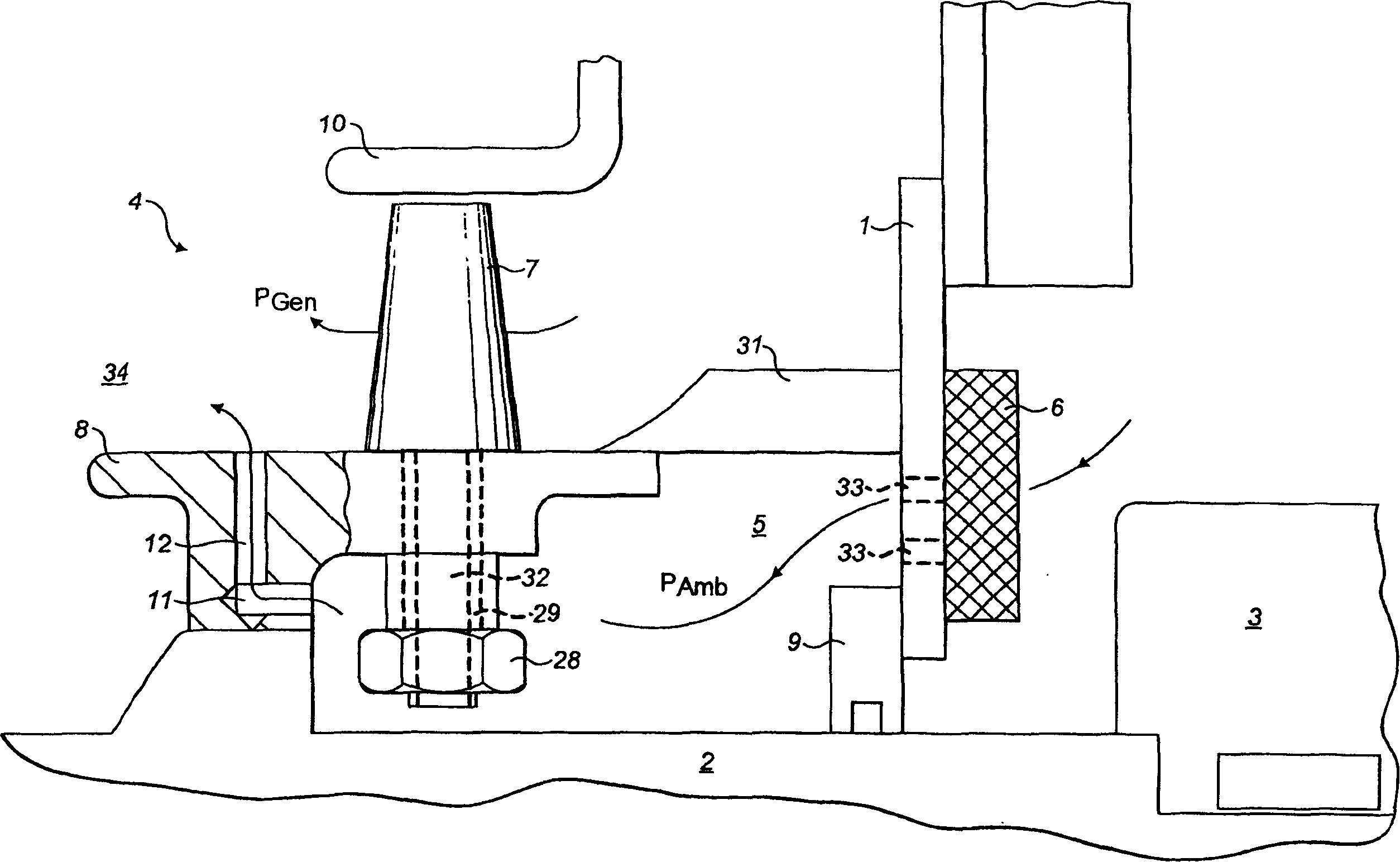
[0034] figure 1 The first embodiment showing the advantages of the supercharging device on the axial fan of the gas-cooled turbo-generator is shown, in which, figure 1 Only the components important to the supercharging device are schematically shown.

[0035]The turbine generator has a closed cooling circuit. As the cooling medium, air is preferably used. The flow direction of the circulating cooling medium is indicated by the streamline of the directional arrow in the drawing, and is basically distributed from right to left in the plane of the drawing. The turbo-generator has a partially illustrated generator casing 1 made of steel plate, which completely houses the generator itself (not shown) and the axial fan 4 for cooling medium circulation therein.

[0036] In this regard, the axial fan 4 is arranged on the rotor shaft 2, which is supported in bearings 3 on the outside of the generator casing 1. The shaft outlet is sealed from the outside through the shaft seal 9. The axi...


PUM


Abstract

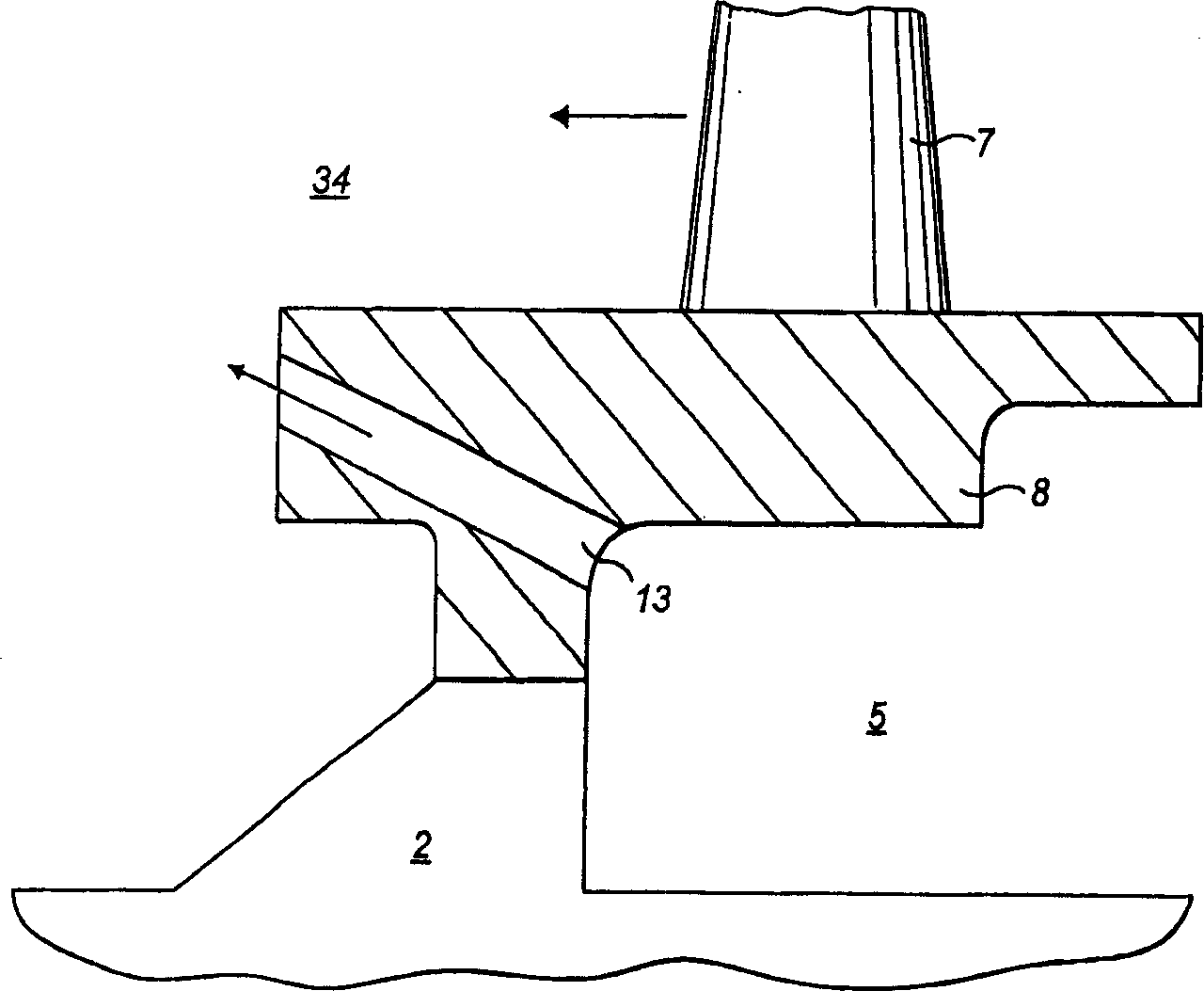
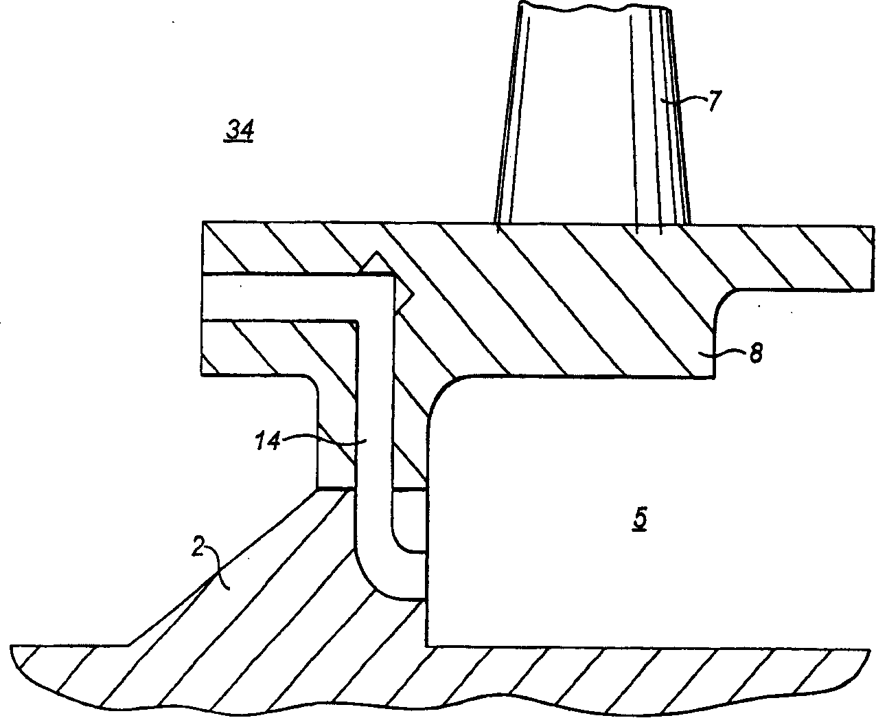
A gas-cooled electric machine, particularly an air-cooled turbo-generator, having a rotor shaft ( 2 ) on which there is at least one axial fan ( 4 ) inside a generator housing ( 1 ), characterized in that a pressure boosting means for raising the absolute pressure in the generator interior ( 34 ) is provided on the axial fan ( 4 ), said means having at least one flow channel ( 11, 12 ) between the hub interior ( 5 ) that is delimited by the hub ( 8 ) of the axial fan ( 4 ) and the generator interior ( 34 ), whereby the flow inlet and the flow outlet of the flow channel are radially at a distance from each other. As a result, an improved gas-cooled electric machine is created which achieves a marked increase in the absolute pressure in the generator housing. The higher density of the cooling medium attains improved heat dissipation and thus more effective cooling of the generator. In this context, no additional external devices to raise the pressure or external control devices are needed, but rather, only modifications to the already existing fan module, which is why the invention is also well-suited for easily retrofitting existing generators.

Description

Technical field [0001] The invention relates to a gas-cooled electric machine, in particular an air-cooled turbo-generator with a closed cooling circuit, with a rotor shaft on which at least one axial fan is arranged inside the generator casing. Background technique [0002] The three-phase AC turbine generator is driven by a steam turbine or a gas turbine in a known manner. The rotor of a turbine generator is usually composed of a solid cylindrical forged steel part, which distributes the field windings in a single slot. Here the rotor rotates in the hole of the stator of the generator. The stator consists of a sheet metal part, which on its side has slots for accommodating the armature winding. The key to the design and structure of this turbo-generator is cooling technology, because it can increase the power. The current turbine generators generally use gaseous cooling medium and a fan installed on the rotor for the cooling medium to circulate inside the generator. [0003] EP...

Claims


Application Information

Patent Timeline
Patent Type & Authority Applications(China)
IPC IPC(8): H02K9/04H02K9/06
CPCH02K9/06
Inventor R·约霍
Owner ALSTOM TECH LTD
Learn More