Optical fibers and processes and apparatus for making the same

Inactive Publication Date: 2001-06-26
ROGER K HUGHES AS SUCCESSOR & TRUSTEE
View PDF10 Cites 10 Cited by
  • Summary
  • Abstract
  • Description
  • Claims
  • Application Information

AI Technical Summary

Benefits of technology

It is an advantage of the present invention to increase the absolute pressure exerted upon the polymerizing mass to reduce the number of voids and bubbles thereby improving the light transmitting properties.
It is a further advantage of the present invention to utilize relatively thin wall claddings to contain the pressurized polymerizing mass and without the need for a manufacturing jacket.
It is a feature of the present invention to provide an inner pressure upon the interior of the cladding containing the polymerizing mass and an outer pressure upon the exterior of the cladding in which the inner pressure is higher relative to the exterior pressure thereby creating a pressure differential.
The present invention is directed to an improved LCPOF with improved light transmitting properties in the light transmitting core and an improved batch process and reactor for pressuring the polymerizing mass to reduce the bubbles and voids in the light transmitting core thereby providing improved optical properties. The batch process of the present invention utilizes a cladding and polymerizing mass in a reactor in which an inner pressure is applied to the interior chamber of the cladding containing the polymerizing mass and an exterior pressure is applied to the outer surface of the cladding. The exterior pressure has a value less than the interior pressure resulting in a pressure differential between the interior and exterior pressures.
The press

Problems solved by technology

Claddings are usually made of materials which are rather expensive and at times difficult to handle.
The present batch methods of production can cause imperfections at the core-clad interface when the core becomes separated from the cladding during and after polymerization.
Furthermore, voids and bubbles may form in the light transmitting core during formation.
Separation of the light transmitting core from the cladding as well as the formation of voids and bubbles reduce light transmission and are undesirable.
Nonetheless, fluoropolymers are relatively expensive ($0.03 to 0.04/gr.
Nonetheless, fluoropolymer claddings with such thin walls, even when encased in a relatively thick manufacturing jacket, deform during the core manufacturing.
Another cause of de-lamination is where a cla

Method used


Image

  • Optical fibers and processes and apparatus for making the same
  • Optical fibers and processes and apparatus for making the same

Examples


first embodiment

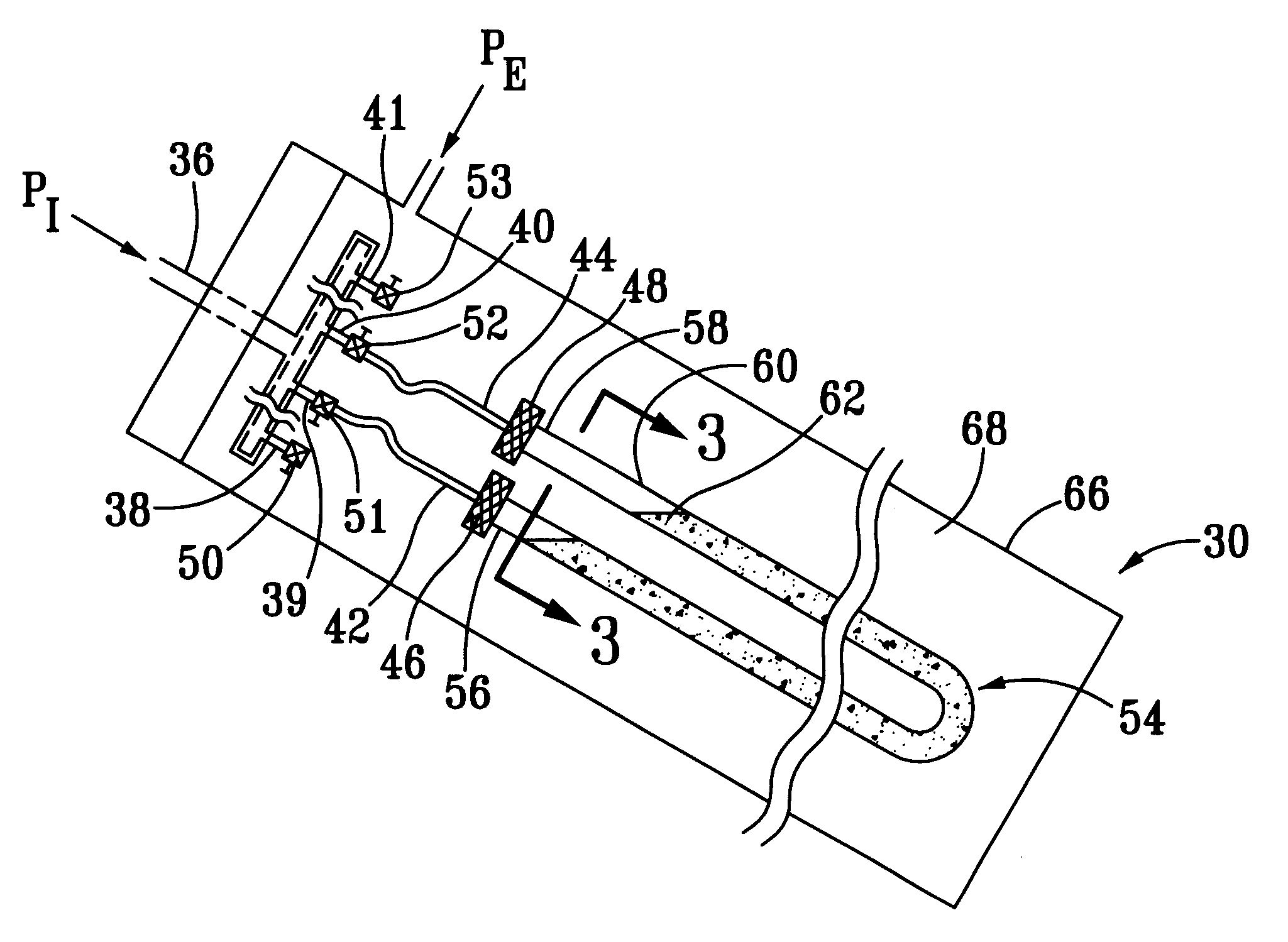
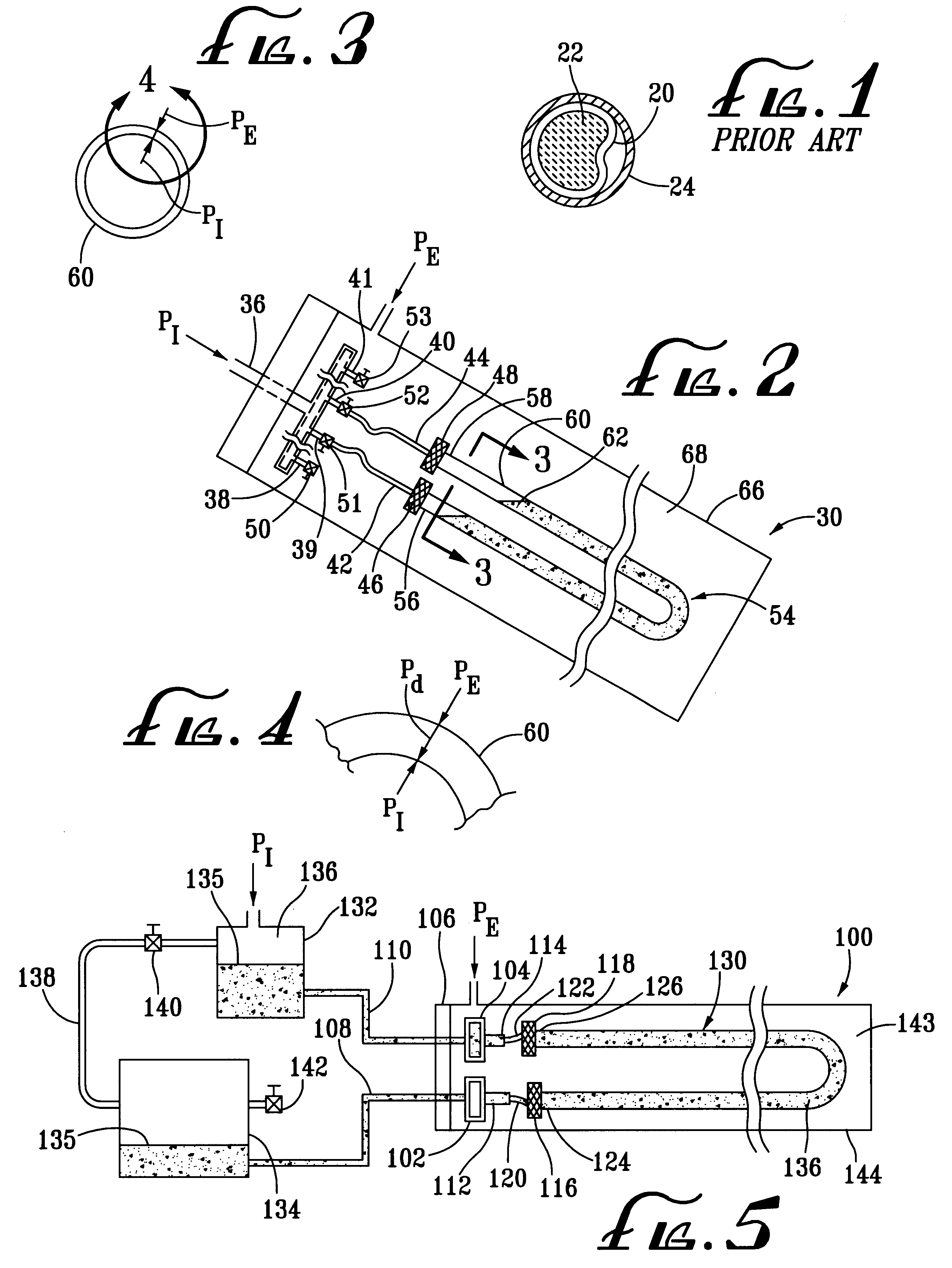
In a first embodiment, a reactor 30 as set forth in U.S. Pat. No. 5,122,580 is modified as shown in the diagram of FIG. 2. The closing hatch 32 of the reactor is fitted with a manifold 34 having an inlet tube 36 and outlet tubes 38-41, tubing extensions 42 and 44, conventional compression fittings 46 and 48 and conventional valves 50-53 on the outlet tubes, and for connection to the open ends of one or more cladding assemblies 54 with any suitable, conventional means. Only one cladding assembly 54 is illustrated in FIG. 2. The fittings 46 and 48, tubing extensions 42 an 44 and valves 51 and 52 connect the open ends 56 and 58 of the cladding assembly 54 including a cladding 60 filled with a monomer mixture 62 through the outlet tubes 39 and 40 of the manifold 34. The manifold 34 provides a passageway between the cladding ends 56 and 58 and the inlet tube 36. The inlet tube 36 connects to a conventional pressure source (not shown), preferably, comprising an inert gas, such as nitrogen...

second embodiment

a reactor 100 as illustrated by FIG. 5 utilizes the full length of the cladding(s). During the polymerization reaction, 10-15% of the volume of the monomer mixture is lost. For instance, typically, a 35 m length of cladding is used to obtain a final optic length of 30 m. The unused 5 m of the cladding is thereafter discarded. It is desirable to prevent the loss of cladding material. With reference to FIG. 5, two manifolds 102 and 104 are attached to the hatch 106, each having an inlet tube 108 and 110 and outlet tubes 112 and 114. The outlet tubes 112 and 114 connect through fittings 116 and 118 and tubing extensions 120 and 122 to respective ends 124 and 126 of a cladding assembly 130. Two exterior tanks 132 and 134 connect to the inlet tubes 108 and 110 of the manifolds 102 and 104. A first or inlet tank 132 is large enough to contain the monomer mixture 135 needed for the reaction. A second or outlet tank 134 is large enough to hold any excess mixture 135. Once the cladding assem...

example 1

An FEP Teflon.RTM. cladding with a an inside diameter (ID) of approximate 11 mm and a wall thickness of 0.51 mm was heat expanded to an approximate internal diameter of 12 mm and wall of 0.46 mm and jacketed with a manufacturing jacket made of poly(ethylene) having an approximate wall thickness of 1.8 mm. A 35 m length of this cladding and manufacturing jacket combination was filled with a monomer mixture of approximately 50 parts by volume of highly purified (distilled under vacuum) methyl methacrylate, 50 parts by volume of CR-39 manufactured by PPG, Ind. of Pittsburgh, Pa. and initiated with 0.6 parts by volume of isopropyl peroxide. The cladding filled with the monomer mixture was formed into a U shape and placed inside a reactor as described in U.S. Pat. No. 5,225,166. The reactor was modified to the first embodiment as illustrated by FIG. 2 herein. The cladding assembly was attached using fittings of the compression fitting type manufactured by Swagelock.RTM. of Solon, Ohio.

Th...


PUM

PropertyMeasurementUnit
Areaaaaaaaaaaa
Areaaaaaaaaaaa
Areaaaaaaaaaaa

Abstract

A large core polymeric optical fiber having improved light transmitting characteristics includes a cladding filled with a light transmitting core. The core is formed during a polymerization reaction within the cladding in which the pressure internal to the cladding is greater than the pressure external to the cladding to form a pressure differential supported by the cladding.

Description

A. Field of the InventionThe present invention relates to optical fibers, and an improved process and apparatus for production of the same. More particularly, the present invention relates to optical fibers having good optical properties and improved apparatus and batch process for production of the same.B. Description of the Related ArtIn the production of Large Core Polymeric Optical Fibers (LCPOF), two processes are known for such production: (1) batch and (2) continuous. The present invention is described using the batch process that uses claddings to essentially provide a mold for the light transmitting core. During the batch process, the claddings are filled with highly purified monomer mixtures and placed inside a reactor where polymerization of the monomer mixture occurs. Claddings are usually made of materials which are rather expensive and at times difficult to handle. Therefore, there is a desire to reduce cladding costs through thinner cladding walls as well as using oth...

Claims


Application Information

Patent Timeline
IPC IPC(8): B29C39/40B29C39/22B29C39/44B29D11/00
CPCB29C39/405B29C39/44B29D11/00663B29C2791/007
Inventor ZARIAN, JAMES R.DILL, SCOTT D.
Owner ROGER K HUGHES AS SUCCESSOR & TRUSTEE
Why Eureka
Try Eureka