
Velocity modulation coil apparatus and cathode-ray tube apparatus

A technology for cathode ray tubes and coil devices, applied in the direction of cathode ray tubes/electron beam tubes, electrode devices and related components, discharge tubes, etc., can solve the problem of increased impedance of speed modulation coils, unrealized, increased cost of drive circuits, etc. question

Inactive Publication Date: 2005-12-14
MATSUSHITA TOSHIBA PICTURE DIS
View PDF3 Cites 0 Cited by
  • Summary
  • Abstract
  • Description
  • Claims
  • Application Information

AI Technical Summary

Problems solved by technology

However, in this case, the impedance of the speed modulating coil increases, and thus, a large power must be applied to the speed modulating coil, which leads to an increase in the cost of the driving circuit.
[0012] Therefore, the method of improving the enhancement effect of the image edge through the speed modulation coil without increasing the driving power has not yet been realized.

Method used


Image

  • Velocity modulation coil apparatus and cathode-ray tube apparatus
  • Velocity modulation coil apparatus and cathode-ray tube apparatus
  • Velocity modulation coil apparatus and cathode-ray tube apparatus

Examples


Embodiment Construction

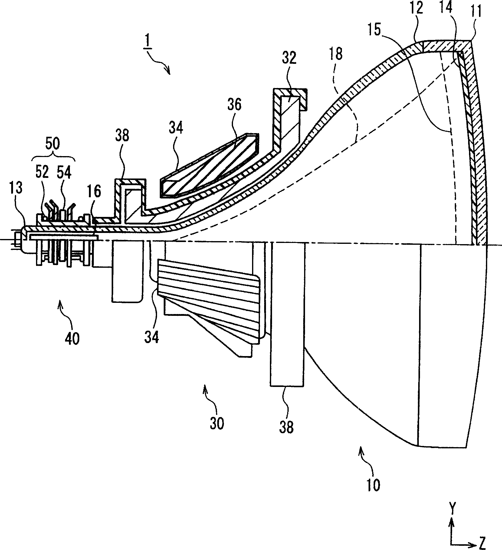
[0027] According to the present invention, the magnetic resistance with respect to the magnetic flux generated by the pair of speed modulation coils is reduced by the pair of magnetic bodies. Therefore, the magnetic flux density of the electron beam passing region within the neck can be increased. Therefore, the sensitivity of speed modulation can be increased without increasing the driving power, so that the image quality can be improved due to the enhancement of the image edge.

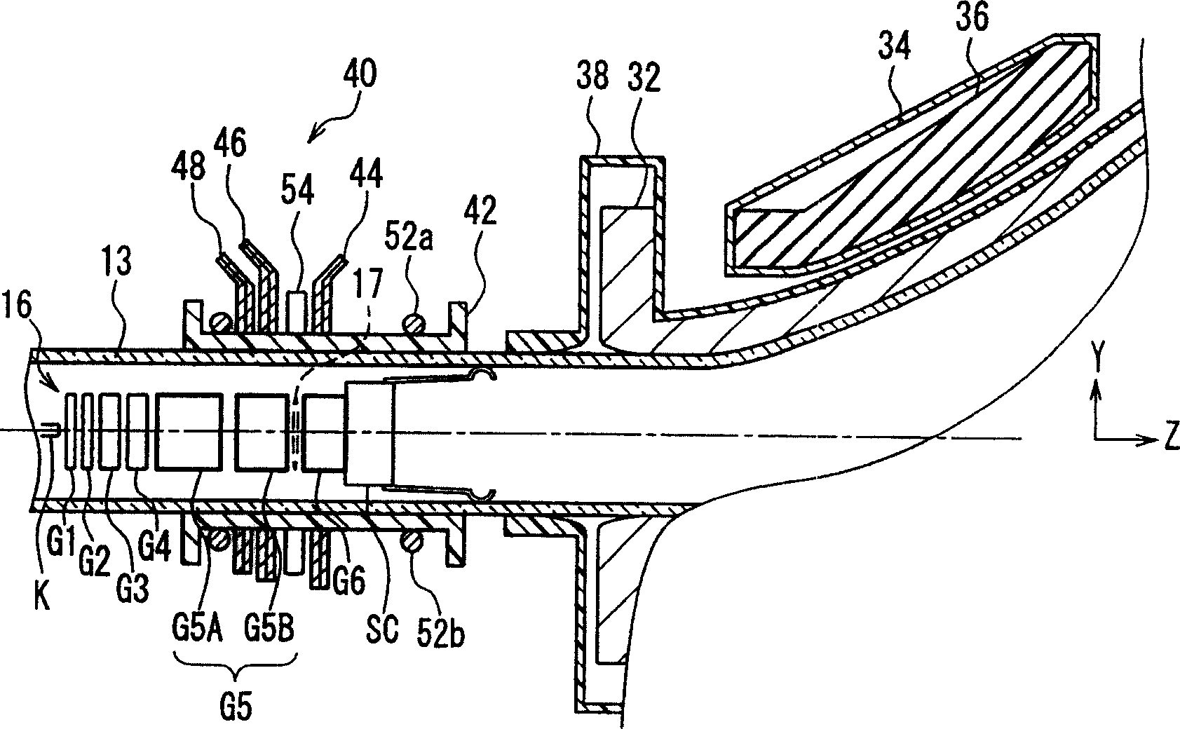
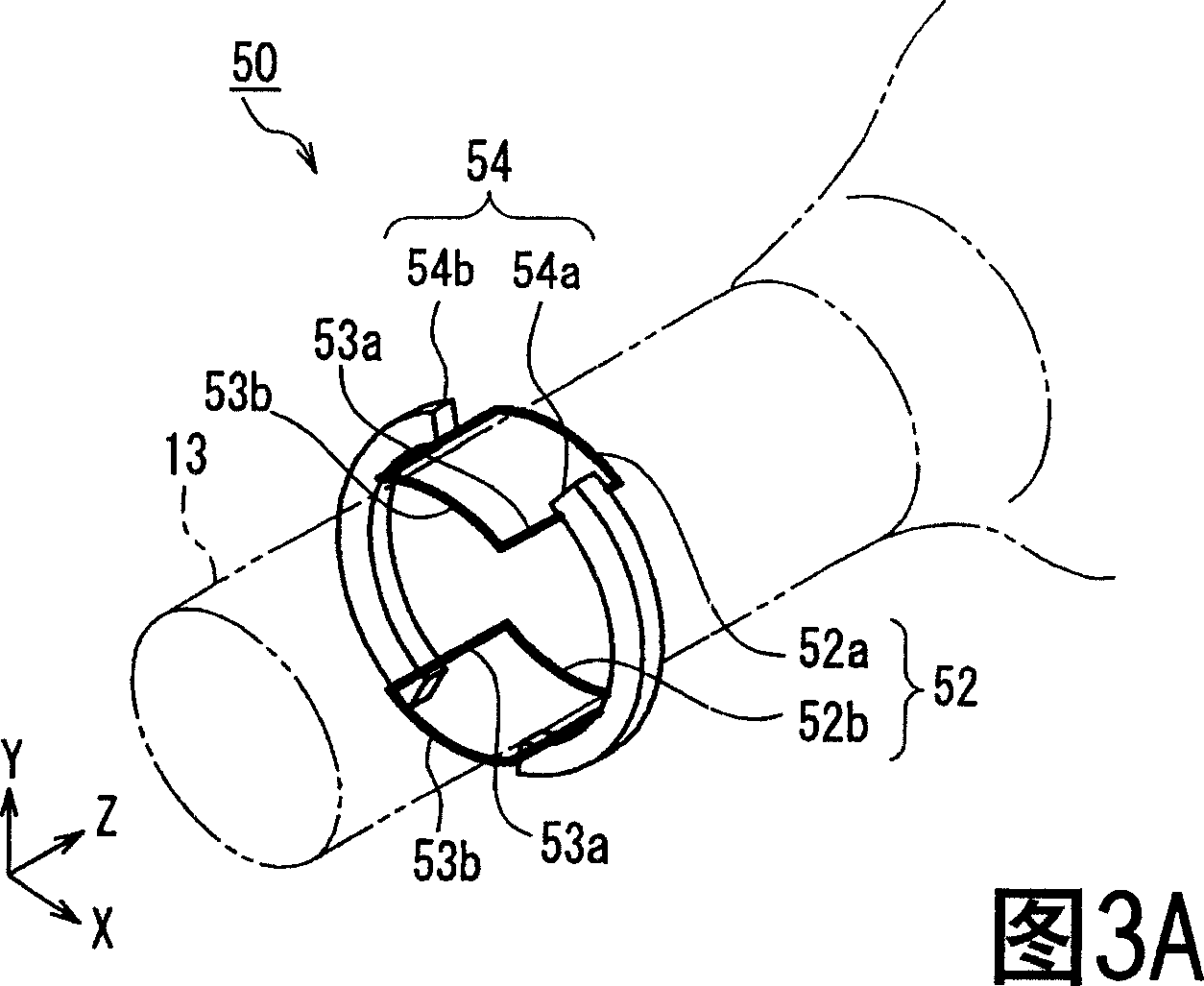
[0028] In the present invention, preferably, an angle θ of one opening between the pair of magnetic bodies with respect to the tube axis of the cathode ray tube is 50° to 90°. According to the above structure, the sensitivity of speed modulation can be further improved, and at the same time, new image distortion and misconvergence caused by the existence of the pair of magnetic bodies can be reduced.

[0029] Preferably, the length H of the magnetic body in the axial direction of the ray tube is 2 ...


PUM


Abstract

A pair of speed modulating coils (52a, 52b) are placed in such a way that a horizontal plane containing the axis of the tube is located between them, and a pair of magnetic bodies (54a, 54b) are positioned in such a way that a plane containing the axis of the tube A vertical face is located between them. A straight portion (53a) of the speed modulating coil extending substantially parallel to the tube axis is placed between the magnetic body and the tube axis. The distance D between the magnetic body and the straight portion (53a) is 1 to 3 mm. Assuming that the axis of the ray tube is the Z axis, the size of the speed modulating coil on the axial direction of the ray tube is L, and the position of the end of the speed modulating coil on the side opposite to the fluorescent screen in the axial direction of the ray tube is Z=0, then The center point of the tube axial direction of a pair of magnetic bodies (54a, 54b) is located in the range of Z=0.2*L to 0.9*L. Therefore, the sensitivity of speed modulation can be improved with a simple structure while suppressing an increase in driving power.

Description

technical field [0001] The present invention relates to a cathode ray tube device for use in television receivers, computer monitors and the like. The invention also relates to a velocity modulating coil arrangement to be mounted on said cathode ray tube arrangement. Background technique [0002] As a method for achieving higher image quality in television receivers, for example, enhancement of image edges is known. To enhance the image edges, velocity-modulated coils are used. The speed modulating coil is arranged on or near the neck of the cathode ray tube, and generates a magnetic field in the vertical direction to modulate the horizontal scanning speed of the electron beam, thereby enhancing the edge of the image (for example, see Japanese Publication No. 57-45650 and Japanese Patent Application Laid-Open No. 6-283113). [0003] In color cathode ray tube devices, as the diameter of the electron beam spot on the fluorescent screen increases due to the enlargement of th...

Claims


Application Information

Patent Timeline
Patent Type & Authority Applications(China)
IPC IPC(8): H01J29/76
CPCH01J2229/5688
Inventor 谷轮贤一郎佐藤明岩崎胜世
Owner MATSUSHITA TOSHIBA PICTURE DIS
Learn More