Method for transmitting line signal via line equipment and transmitting equipment

A line signal and line equipment technology, applied in line transmission components, telephone communication, and the limit level depends on the signal/carrier strength, etc., which can solve the problems of expensive, complex design, and highly complex protection equipment

Inactive Publication Date: 2005-12-14
LANTIQ BET GMBH & CO KG
View PDF0 Cites 2 Cited by
  • Summary
  • Abstract
  • Description
  • Claims
  • Application Information

AI Technical Summary

Problems solved by technology

Disadvantageously, such protective elements are expensive and such protective devices using them are highly complex
There is also the disadvantage that traditional external protection elements have a complex design

Method used


Image

  • Method for transmitting line signal via line equipment and transmitting equipment
  • Method for transmitting line signal via line equipment and transmitting equipment
  • Method for transmitting line signal via line equipment and transmitting equipment

Examples


Embodiment Construction

[0042] In the drawings, the same reference symbols indicate components or steps that are the same or have the same function.

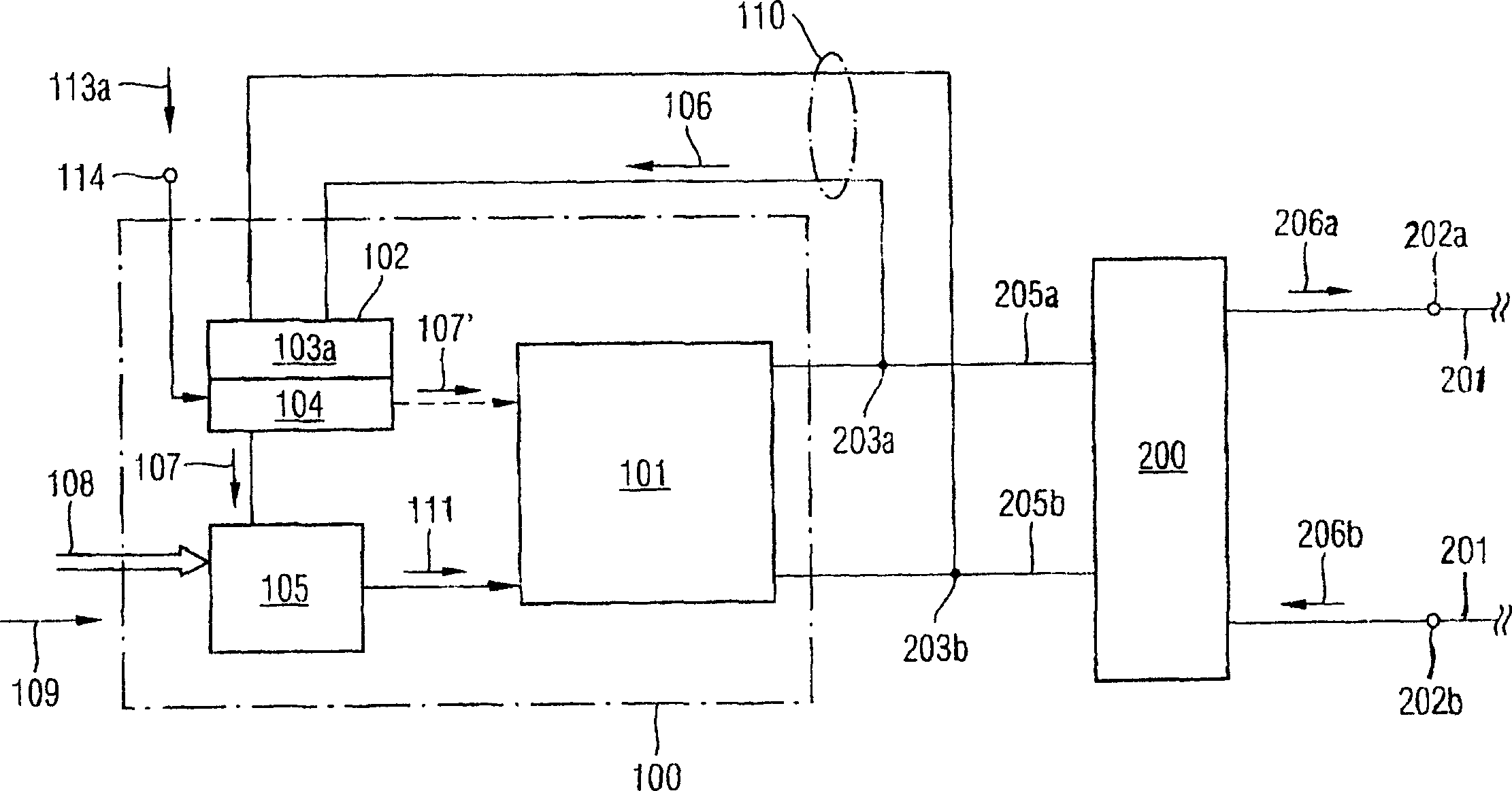
[0043] figure 1 A block diagram of a preferred exemplary embodiment of the line signal transmission device of the present invention is shown.

[0044] Such as figure 1 As shown, the line driver device 100 is connected to the line device 201 via output connections 202a, 202b. Between the line driven device 100 and the output connections 202a, 202b, there is an external protection device 200, having a simplified design compared to conventional external protection devices, for protection against overvoltage of the line driven device (see Figure 4 ). The line driver device 100 is connected to an external protection device 200 via connection lines 205a, 205b. The line device 201 is used to drive line signals 206a, 206b.

[0045] In the line driving device 100 of the present invention, basic components are represented by blocks. In this context, refe...


PUM


Abstract

The present invention proposes a transmission device for a line signal (206a, 206b), having a line device (201) for transmitting the line signal (206a, 206b) at a specified signal level; and a line driving device (100), It has an amplification unit (101) and a control unit (105). When the signal level of the line signal (206a, 206b) exceeds the specified reference level (113a, 113b), by having determined that the signal level of the line signal (206a, 206b) exceeds the specified reference signal level (113a, 113b) A determination unit (102) is used to switch the operation mode of the amplification unit (101) using the determination unit (102).

Description

technical field [0001] The present invention relates generally to a line driving device, also known as a Subscriber Line Interface Circuit (SLIC), and more particularly to a line signal transmission device for transmitting line signals at specified signal levels. [0002] In particular, the present invention relates to a line signal transmission device having a line device for transmitting a line signal at a specified signal level and a line driving device having: [0003] - an amplification unit for amplifying the line signal to be driven into the line device to a specified signal level; and [0004] - a control unit for controlling the operation mode of the amplifying unit with an operation mode control signal output from the control unit. Background technique [0005] Figure 4 A conventional line driver LT transmitting line signals via a transmission line L is shown. The line driver LT has an output stage AS for providing a specifiable level for the line signal to be d...

Claims


Application Information

Patent Timeline
Patent Type & Authority Applications(China)
IPC IPC(8): G11C7/10H02H9/02H02H9/04H03G11/04H03G11/08H04B3/02H04L12/66H04M3/00
CPCG11C7/1051G11C7/1057G11C7/1069G11C7/1078G11C7/1084G11C7/1096
Inventor 彼得·卡尔德拉托马斯·费里安茨
Owner LANTIQ BET GMBH & CO KG
Why Eureka
Try Eureka