Travelling wave driven prezoelectric ceramic pump capable of realizing forward-reverse fluid flow

A piezoelectric ceramic pump and fluid flow technology, used in pumps, machines/engines, liquid variable capacity machines, etc., can solve problems such as single means, and achieve the effects of safe and reliable work, reduced mechanical wear, and convenient operation.

Inactive Publication Date: 2005-12-21
TSINGHUA UNIV +1
View PDF0 Cites 8 Cited by
  • Summary
  • Abstract
  • Description
  • Claims
  • Application Information

AI Technical Summary

Problems solved by technology

Moreover, the flow control method of traditional piezoelectric pumps is relatively simpl

Method used


Image

  • Travelling wave driven prezoelectric ceramic pump capable of realizing forward-reverse fluid flow
  • Travelling wave driven prezoelectric ceramic pump capable of realizing forward-reverse fluid flow
  • Travelling wave driven prezoelectric ceramic pump capable of realizing forward-reverse fluid flow

Examples


Embodiment 1

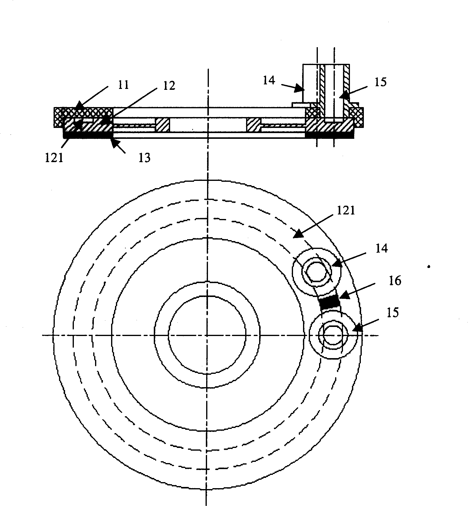
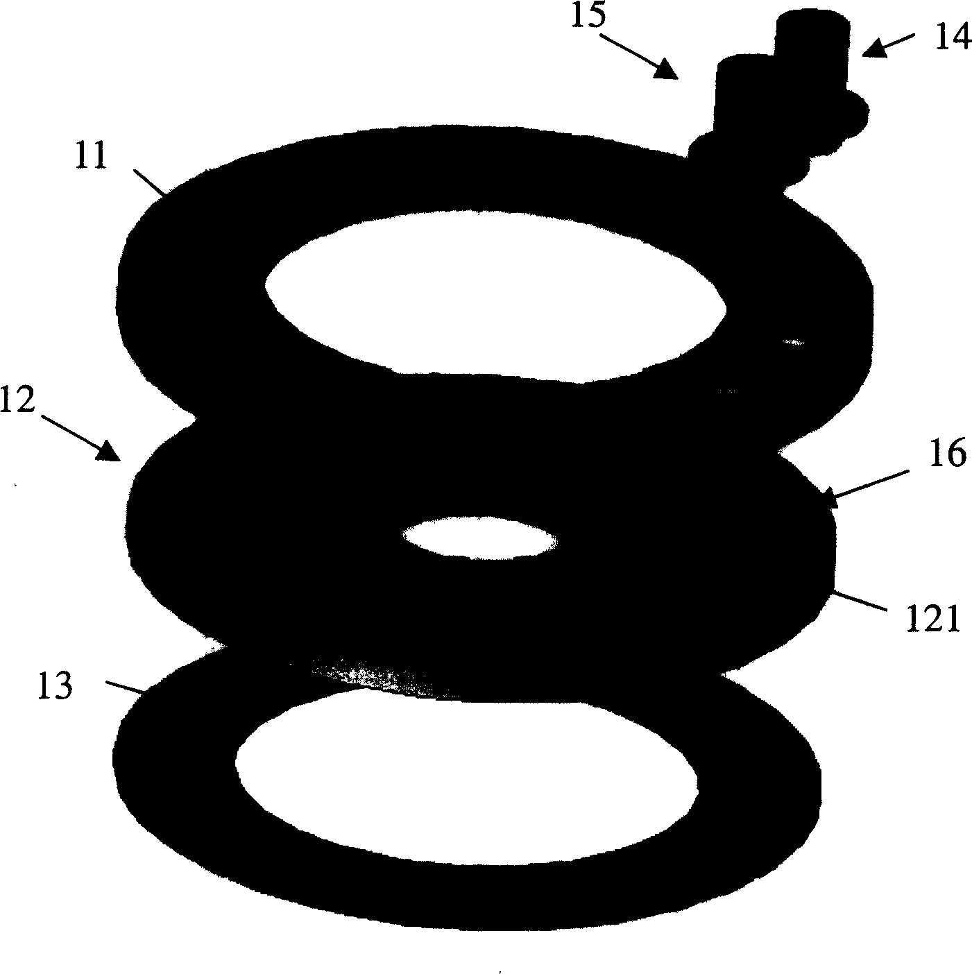
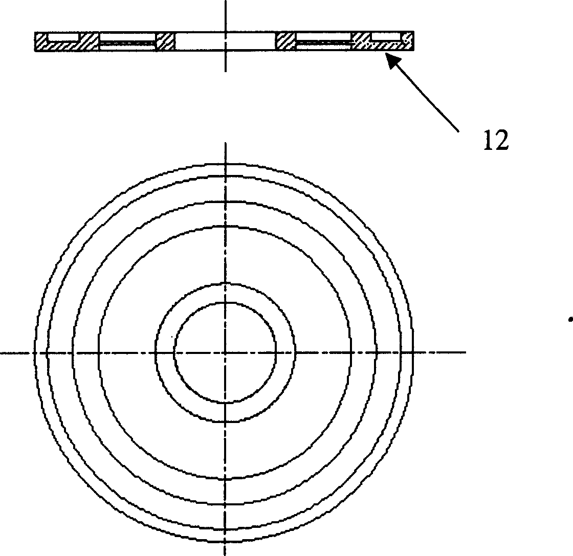
[0056] The present invention has designed the first embodiment of the traveling wave driven piezoelectric ceramic pump, such as Figure 1-6 shown. In this embodiment, the traveling-wave driven fluid piezoelectric pump is connected to the pump body 12 by the pump cover 11 with the inlet port 14 and the outlet port 15, and the bottom end of the pump body 12 is bonded with a piezoceramic ring piece 13. A block 16 is disposed in the groove 121 . It is characterized in that: on the upper side of the outer circumference of the pump body 12, there are circumferentially distributed grooves 121, the cross section of the groove is rectangular, the three end faces of the rectangle rely on the pump body 12, and the upper end faces rely on the pump cover 11 for sealing. On the lower side of the outer circumference of the pump body 12, a piezoelectric ceramic ring piece 13 is adhered. The inlet port 14 and the outlet port 15 are glued and fixed on the same side of the pump cover 11, and t...

Embodiment 2

[0061] The present invention has designed the second embodiment of the traveling wave driven piezoelectric ceramic pump, as Figure 7-8 shown. In this embodiment, the traveling-wave driven fluid piezoelectric pump is connected to the pump body 72 by a pump cover 71 with an inlet port 74 and an outlet port 75. The bottom end of the pump body 72 is bonded with a piezoelectric ceramic ring piece 73. A block 76 is disposed in the groove 721 . It is characterized in that: there are circumferentially distributed grooves 721 on the upper side of the outer circumference of the pump body 72 , the cross section of the groove is rectangular, the three ends of the rectangle rely on the pump body 72 , and the upper end faces rely on the pump cover 71 for sealing. On the lower side of the outer circumference of the pump body 72, a piezoelectric ceramic ring piece 73 is adhered. The inlet port 74 and the outlet port 75 are glued and fixed on the same side of the pump cover 71, and the inle...

Embodiment 3

[0065] The present invention has designed the third embodiment of the traveling wave driven piezoelectric ceramic pump, as Figure 9-10 shown. In this embodiment, the traveling-wave driven fluid piezoelectric pump is connected to the pump body 92 by the pump cover 91 with the inlet port 94 and the outlet port 95, and the bottom end of the pump body 92 is bonded with a piezoelectric ceramic ring piece 93. A block 96 is disposed in the groove 921 . It is characterized in that: there are circumferentially distributed grooves 921 on the upper side of the outer circumference of the pump body 92 , the cross section of the groove is rectangular, the two end faces of the rectangle rely on the pump body 92 , and the other two end faces rely on the pump cover 91 for sealing. A piezoceramic ring sheet 93 is glued to the lower side of the outer circumference of the pump body 92 . The inlet port 94 and the outlet port 95 are glued and fixed on the same side of the pump cover 91, and the ...


PUM


Abstract

The invention relates to flow pump technique field in precise machine which features that the circle edge of pump body is processed with slots on both upper and lower side, and with several through holes in slots; the slot is sealed by upper and lower pump cover forming a flow channel; upper and lower piezoelectric ceramic plate pasted respectively on the upper and lower side of the pump body, moreover the upper and lower pieces is one fourth wavelength different along the circle, generating a needed traveling wave fluctuate in upper and lower slots while working; flow inlet port and outlet port placed on the same or different sides of the ceramic pump, and block is just between the two port ensuring the flow enters from the inlet port and leaves from the outlet port. The flow direction is controlled by the phase difference of the two exterior power source while the flow amount, speed and back pressure with width, frequency and phase position. It is of low sealing requirement, high reliability, fine flow block performance, handily operation and the working frequency is above 10 KHz.

Description

technical field [0001] The invention belongs to the technical field of fluid pumps in precision machinery, and in particular relates to the specific structural design, manufacturing method and driving method of a novel piezoelectric ceramic pump driven by traveling waves. technical background [0002] In the background technology, most of the traditional piezoelectric pumps use the bending deformation of the low-order modes of piezoelectric ceramics, which leads to the change of the volume of the pump cavity, and squeezes the liquid in the cavity to form the flow of the liquid. Its working principle determines that there are relatively high requirements for design, assembly and use of piezoelectric pumps. For example, the pump cavity is required to be highly sealed to avoid air bubbles in the cavity. The existence of air bubbles will directly affect the pumping effect of the piezoelectric pump, and even easily cause the piezoelectric pump to fail to work normally. Before mo...

Claims


Application Information

Patent Timeline
IPC IPC(8): F04B17/00
Inventor 褚祥诚袁松梅李龙土
Owner TSINGHUA UNIV
Why Eureka
Try Eureka