Spiral fan and air conditioner therewith

A screw type and fan technology, applied in air conditioning systems, parts of pumping devices for elastic fluids, applications, etc., can solve the problems of reduced commerciality and performance degradation, and achieve improved commerciality, suppressed noise, and improved comfort Effects on Sex and Convenience

Inactive Publication Date: 2005-12-28
SAMSUNG ELECTRONICS CO LTD
View PDF1 Cites 2 Cited by
  • Summary
  • Abstract
  • Description
  • Claims
  • Application Information

AI Technical Summary

Problems solved by technology

Therefore, the noise generated by these conflicts not only leads to lowering of commerciality, but also leads to lowering of performance due to the loss of useless work generated.

Method used


Image

  • Spiral fan and air conditioner therewith
  • Spiral fan and air conditioner therewith
  • Spiral fan and air conditioner therewith

Examples


Embodiment Construction

[0054] The helical fan and the air conditioner using the fan according to the embodiment of the present invention will be described below with reference to the accompanying drawings.

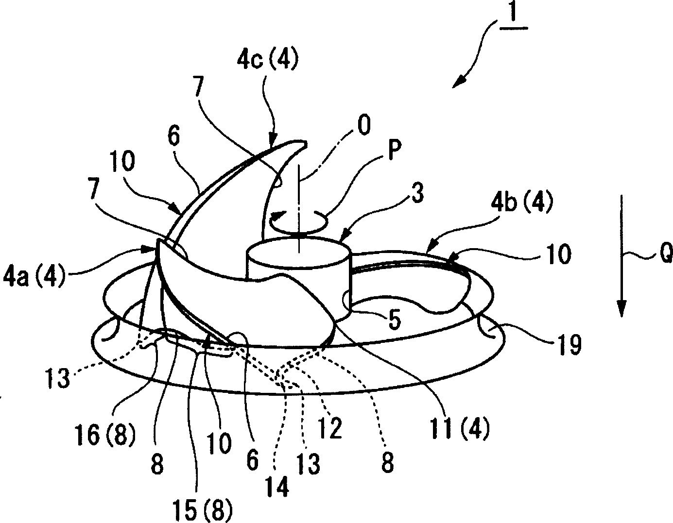
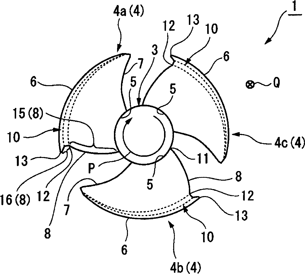
[0055] figure 1 It is a perspective view of the helical fan according to the first embodiment of the present invention; figure 2 to press figure 1 Plan view of the helical fan shown.

[0056] As shown in the above figure, the helical fan 1 according to this embodiment has a cylindrical center 3 and blades 4 ( 4 a - 4 c ) provided on the center 3 . Rotate the hub 3 in the prescribed direction P (clockwise at this time) to rotate the fan blades 4 and discharge fluids such as air from the front to the rear (arrow Q direction).

[0057] Each wing 4 has a curved portion 10 ( figure 2 surface side). Such as figure 2 As shown, when the trailing edge line 8 of each fan wing 4 is projected onto a plane perpendicular to the rotation axis 0 of the central hub 3, there is a slow curve drawn from ...


PUM


Abstract

PROBLEM TO BE SOLVED: To provide a propeller fan capable of increasing marketability by preventing noise caused by swirl and increasing performance by suppressing the loss of aerodynamic force and an air conditioner using the propeller fan. SOLUTION: This propeller fan 1 sends out a fluid from an upstream side to a downstream side by rotating a hub 3 to which at least one vane 4 is fitted in a prescribed direction. The outer peripheral part of the vane 4 comprises a curved part 10 curved so that at least a part near its trailing side faces a negative pressure side. The trailing line 8 of the vane 4 is formed in such a curve that advances in the rotating direction while drawing a gentle curve from the inner peripheral end to the outer peripheral side of the vane 4 when projected on a plane perpendicular to the rotating axis O of the hub 3 and retreats in the rotating direction so as to have an inflection point 12 on the slightly root side of the outer peripheral end 13 of the vane 4. COPYRIGHT: (C)2006,JPO&NCIPI

Description

technical field [0001] The invention relates to a spiral fan and an air conditioner using the fan. At least one fan blade is arranged on the center of the fan, and the center is rotated in a prescribed direction so that fluid is discharged from the upstream side to the downstream side. Background technique [0002] As the most basic helical fan available, such as Figure 10 shown. The spiral fan 101 shown in this figure has a cylindrical center 103 and blades 104 ( 104 a - 104 b ) provided on the center 103 . And the central hub 103 is rotated in a prescribed direction P (clockwise at this time), so that fluid such as air is discharged from the front to the rear with the rotation of the fan blade 104 (arrow Q direction). [0003] However, when the fan blade 104 of the spiral fan 101 is rotated, there is a problem that blade tip vortices S1 and S2 occur at the outer peripheral end 106 of the fan blade 104 (refer to Figure 10 ). That is, the wing-e...

Claims


Application Information

Patent Timeline
IPC IPC(8): F04D29/38F04D29/28F04D29/66F24F1/00
CPCF04D29/023F04D29/384F04D29/388F04D29/663F05D2210/12F24F1/0029Y10S415/00Y10S416/00Y10S417/00
Inventor 多久岛朗
Owner SAMSUNG ELECTRONICS CO LTD
Why Eureka
Try Eureka