Power transmission chain

A power transmission and chain technology, applied in the transmission chain and other directions, can solve the problems of sprocket teeth cracks, failures, loud noise of roller chains, etc., and achieve the effect of smooth operation

Inactive Publication Date: 2005-12-28
TSUBAKIMOTO CHAIN CO
View PDF0 Cites 9 Cited by
  • Summary
  • Abstract
  • Description
  • Claims
  • Application Information

AI Technical Summary

Problems solved by technology

[0005] Traditional roller chains tend to be quite noisy in operation and often fail due to cracks forming on their rollers caused by the sprocket teeth interfering with the chain's engagement

Method used


Image

  • Power transmission chain
  • Power transmission chain
  • Power transmission chain

Examples


Embodiment Construction

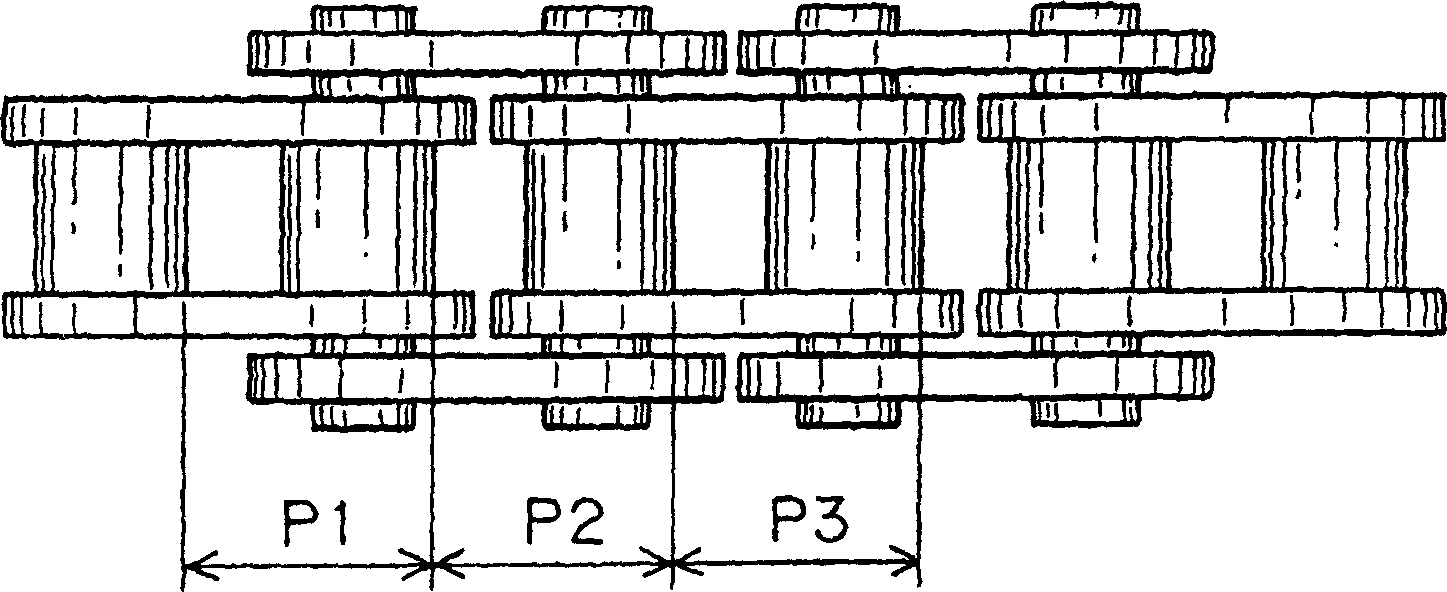
[0013] In the chain 40 according to the present invention, such as Figure 4 Described, the inner and outer links are arranged in overlapping relationship along the length of the chain. Each inner link includes a pair of opposed inner link plates 41 having sleeve holes 41a into which sleeves 42 are press-fitted. The roller 43 is free to rotate on the sleeve. Each outer link includes a pair of opposed outer link plates 44 having pin holes 44a into which pins 45 are press fit. Thus, each inner link comprises two inner links 41 , two bushes 42 and two rollers 43 and each outer link comprises two outer links 44 and two pins 45 . The pin of each outer link extends through the sleeve of the adjacent inner link and is rotatable therein so that the adjacent links can pivot relative to each other.

[0014] Such as figure 2 As shown, in the chain according to the invention, the pitches P1 and P3 are equal to each other. Each of these pitches is measured between corresponding point...


PUM


Abstract

In a newly manufactured roller chain, the pitch measured from one of two adjacent bushings of any two consecutive inner links of the chain to the other is greater than that measured from any of said inner links of the chain The pitch measured from one of the two bushings on one to the other is a small amount corresponding to the initial lengthening of the chain.

Description

technical field [0001] The invention relates to a power transmission chain of this type used in camshaft drives of internal combustion engines, conveyors, power transmissions of industrial machines. Background technique [0002] Roller chains are widely used as a power transmission medium for driving one or more camshafts of internal combustion engines from the engine crankshaft. Metal roller chains are ideal for this application because they exhibit superior durability and can meet the increasing demands of high load capacity, high speed operation, and low maintenance. As a result, roller chains have replaced toothed belts in the synchronous transmission of more powerful automobile engines. [0003] A typical conventional metal roller chain is an endless chain comprising alternately connected and overlapping inner and outer links. Each inner link includes a pair of opposing inner plates and a pair of bushings, each inner plate having a pair of bushing holes, each bushing ...

Claims


Application Information

Patent Timeline
Patent Type & Authority Applications(China)
IPC IPC(8): F16G13/06
CPCF16G13/06
Inventor 户原隆佐藤利文
Owner TSUBAKIMOTO CHAIN CO
Why Eureka
Try Eureka