Plasma display panel

一种显示面板、等离子体的技术,应用在交流电等离子显示板、气体放电电极、气体放电管/容器等方向,能够解决PDP亮室比度差、低吸收效率等问题

Inactive Publication Date: 2005-12-28
SAMSUNG SDI CO LTD
View PDF0 Cites 0 Cited by
  • Summary
  • Abstract
  • Description
  • Claims
  • Application Information

AI Technical Summary

Problems solved by technology

However, this design results in poor bright room contrast for PDPs operating under bright room conditions because of the low absorption efficiency of extraneous light

Method used


Image

  • Plasma display panel
  • Plasma display panel
  • Plasma display panel

Examples


Embodiment Construction

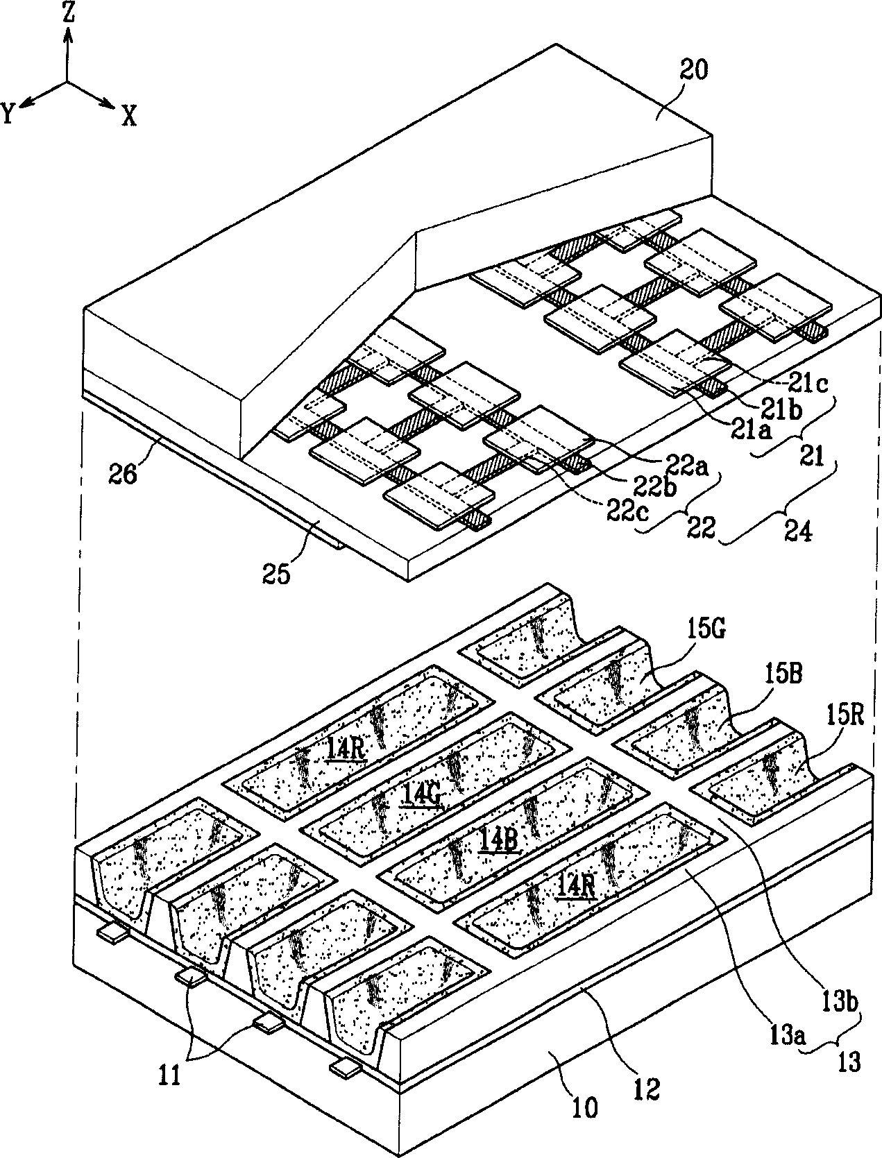
[0022] Such as figure 1 As shown, the PDP according to the present invention includes: a first substrate 10; a second substrate 20 facing the first substrate 10 and separated from the first substrate 10 by a certain distance; discharge cells 14R, 14G, 14B surrounded by barrier ribs 13 , the barrier ribs 13 have a height corresponding to the determined distance between the first substrate 10 and the second substrate 20 .

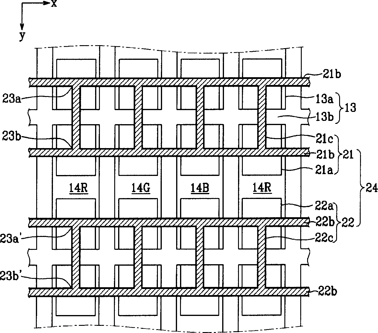
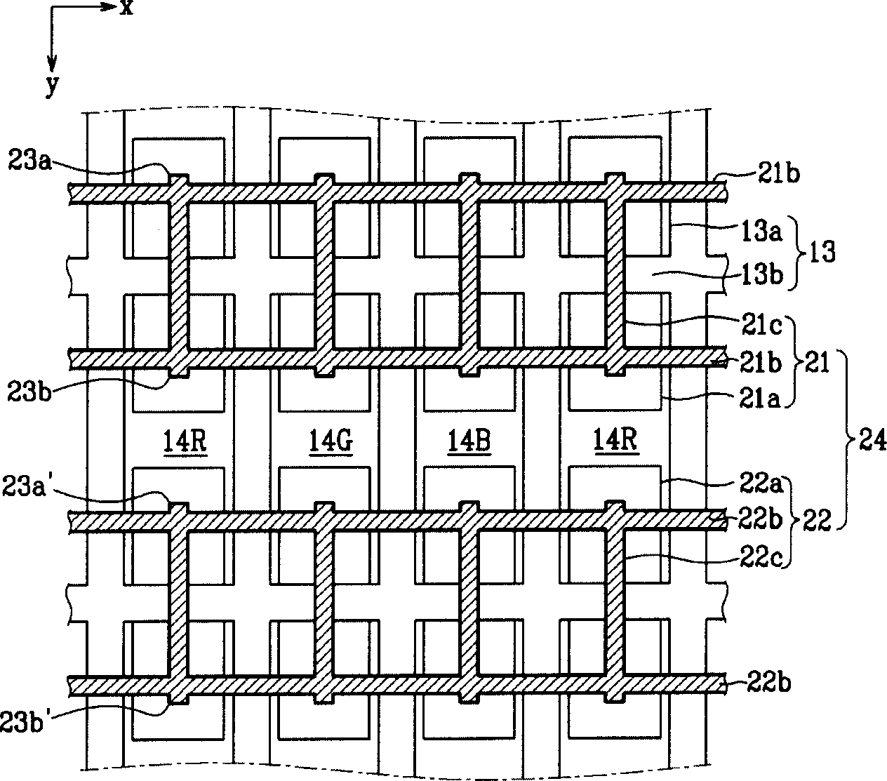
[0023] The barrier ribs 13 include: a first barrier rib member 13a extending in a first direction (y direction in the figure); and a second barrier rib member 13b extending in a second direction (x direction in the figure). The barrier ribs 13 are formed in a lattice pattern and independently define discharge cells 14R, 14G, 14B, which are filled with a discharge gas. R, G, B (red, green, blue) fluorescent layers 15R, 15G, 15B are formed on the four sides of the barrier ribs 13 and the bottoms (-z ends) of the discharge cells 14R, 14G, 14B.

[0024] On the ...


PUM


Abstract

Provided is a plasma display panel (PDP) that improves bright room contrast while achieving a high aperture ratio and high brightness. The PDP includes display electrodes including auxiliary electrodes that suppress reflection of incident light from discharge cells. The address electrodes are formed on the rear substrate, the display electrodes are formed on the front substrate, and the auxiliary electrodes are connected together with the paired display electrodes. The auxiliary electrode and the main bus electrode extend into the discharge cell and reflect external light. Opaque main and auxiliary electrodes are combined with transparent electrode portions covering the main bus and auxiliary electrode portions to form display electrodes.

Description

technical field [0001] The present invention relates to a plasma display panel (PDP), and more particularly to a PDP design that results in improved bright room contrast while maintaining a high aperture ratio and high brightness. Background technique [0002] In general, a PDP is a display device in which ultraviolet rays generated during gas discharge excite phosphor layers to produce visible images. The PDP has attracted attention as a next-generation display device because of its large screen size, thin thickness, and high resolution. [0003] The PDP is classified into a direct current (DC) type and an alternating current (AC) type according to its driving power. One of types of AC PDPs widely used recently is a three-electrode type AC PDP having address electrodes and a pair of display electrodes. [0004] PDPs can also be divided according to the layout of discharge cells in which individual discharges occur. For example, PDPs may be classi...

Claims


Application Information

Patent Timeline
Patent Type & Authority Applications(China)
IPC IPC(8): H01J11/12H01J11/22H01J11/24H01J11/26H01J11/34H01J11/36H01J11/38H01J11/40H01J11/42H01J11/44H01J11/50
CPCH01J11/12H01J11/24H01J2211/245
Inventor 黃义晶李泰昊
Owner SAMSUNG SDI CO LTD
Why Eureka
Try Eureka