Motor driven tool such as a pole hedge trimmer with a locking mechanism for the turnable cutting unit

A technology of electric tools and locking mechanism, applied in cutting tools, cutting equipment, agricultural machinery and implements, etc., can solve the problems of easy detachment of the handle, no control of the cutting device, etc.

Inactive Publication Date: 2005-12-28
HUSQVARNA AB
View PDF1 Cites 11 Cited by
  • Summary
  • Abstract
  • Description
  • Claims
  • Application Information

AI Technical Summary

Problems solved by technology

However this setup is very poor and not advisable from a safety point of view as the lock can

Method used


Image

  • Motor driven tool such as a pole hedge trimmer with a locking mechanism for the turnable cutting unit
  • Motor driven tool such as a pole hedge trimmer with a locking mechanism for the turnable cutting unit
  • Motor driven tool such as a pole hedge trimmer with a locking mechanism for the turnable cutting unit

Examples


Embodiment Construction

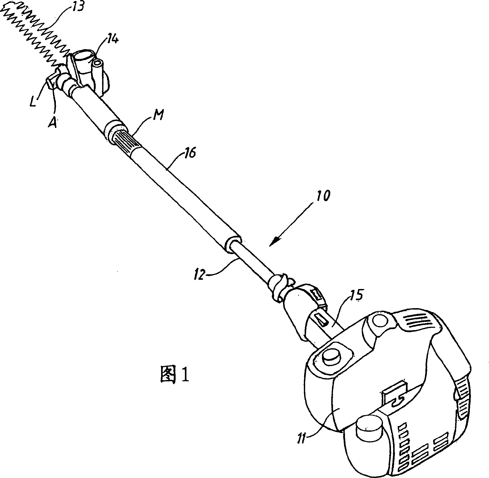
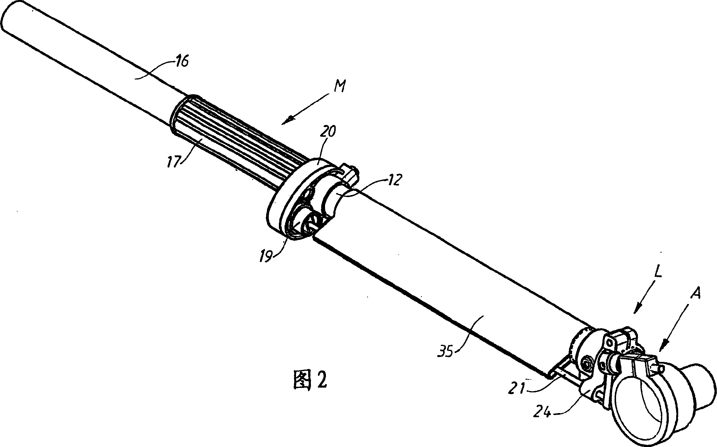
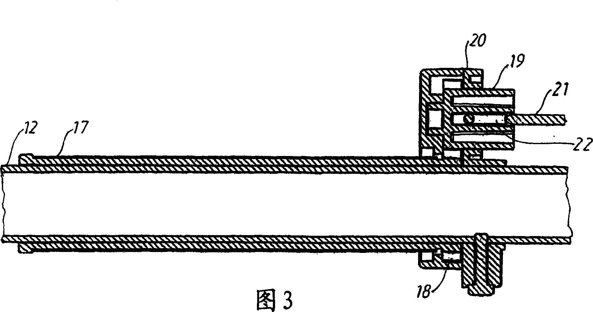
[0014] FIG. 1 shows that the pole hedge trimmer comprises a drive unit 11 connected via a shaft tube 12 to a cutting unit 13 . The driving device 11 can be in various forms, such as an internal combustion engine or an electric motor, the output shaft of which is connected to a drive shaft (not shown), which is arranged in the shaft tube and connected with the cutting device through a gear 14 . The shaft tube 12 has an inner handle 15 and an outer handle 16, the inner handle 15 has a valve (throttle) control device for the driving device and additional control devices, and the outer handle 16 is designed as a sleeve made of a material that is easy to grip. In a conventional manner, the cutting device 13 has a fixed comb-shaped cutter head protector to cooperate with the corresponding cutter head, wherein the cutter head is driven by the drive shaft through the gear 14 and moves back and forth. The cutting device 13 is supported by the shaft tube 12 via a rotatable connection A....


PUM


Abstract

The invention relates to power tools, such as pole hedge trimmers, pole saws or similar tools, comprising a drive unit (1) connected to a cutting unit (13) via a shaft tube (12), said The shaft tube (12) contains a drive shaft and is provided with a handle (16), and the cutting device (13) is rotatably fixed to the shaft tube. The rotatable connection is controlled by a locking mechanism (L) which is released from the operator's normal working position by a control device (M) located at a position away from the locking mechanism (L) and close to the handle (16). Location.

Description

technical field [0001] The present invention relates to power tools, such as pole hedge trimmers, pole saws or the like, comprising a drive unit connected to a cutting unit by means of a shaft tube, the cutting unit being rotatably secured to said shaft tube superior. Background technique [0002] The aforementioned hedge trimmers and saws of this type come with shaft tubes of various lengths and are used for trimming small trees, large trees, hedges, shrubs, etc. These tools have a handle with the necessary controls to operate the drive and a second handle on the shaft tube so that you can find a comfortable work when pruning shrubs, trees and hedges position, since the cutting device can be rotated relative to the shaft tube. This means that the operator is able to set the cutting device in place before work starts, so that the parting or cutting part is adapted to the operator's working position. However, current tool designs place the adjustment mechanism very close t...

Claims


Application Information

Patent Timeline
IPC IPC(8): A01G3/053
CPCA01G3/053
Inventor G·多拉格里普G·达尔贝里
Owner HUSQVARNA AB
Why Eureka
Try Eureka