[0034] (First embodiment)
[0035] Below, according to Figure 1 ~ Figure 5 The first embodiment will be described.
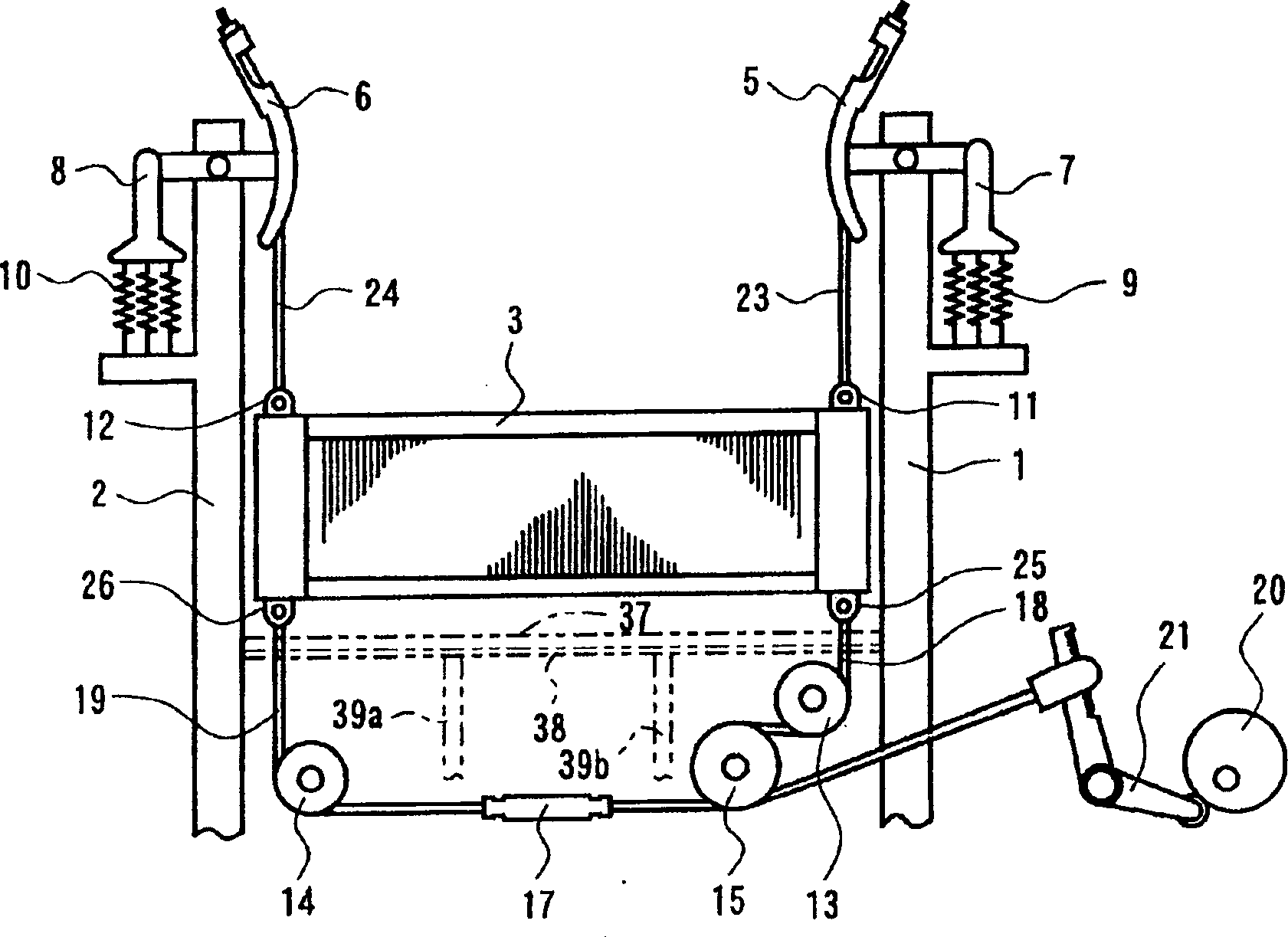
[0036] figure 1 It is a schematic configuration diagram illustrating the passive shedding device of the water jet loom embodying the present invention. A heald frame 3 is provided between the frames 1 and 2, and ropes are attached to the fittings 11, 12 on the upper left and right parts of the aforementioned heald frame 3 23 and 24, the ropes 23 and 24 are connected to the heddles 5 and 6. The spring hangers 7, 8 are locked on the heald rods 5, 6, and the ropes 23, 24 are always in an upward stretched state due to the action of the springs 9, 10.
[0037] In addition, ropes 18, 19 are attached to the fittings 25, 26 at the left and right lower parts of the aforementioned heald frame 3. The ropes 18, 19 go around the guide rollers 13, 14 and the guide roller 15 to be connected to the healds provided on the ground. Frame drive mechanism. A tensioner 17 for adjusting the length of the ropes 18 and 19 and the like are provided in the middle of the aforementioned ropes 18 and 19. The heald frame driving mechanism is composed of a pedal cam 20, a cam lever 21, and the like. The rotation of the pedal cam 20 causes the cam lever 21 to swing, and the ropes 18 and 19 are pulled to pull the heald frame 3 down.
[0038] Between the heald frame 3 and the aforementioned guide rollers 13, 14, 15 and ropes 18, 19 and other transmission components provided below the heald frame 3, an upper pan 37, an intermediate groove 38, and the like described in detail later are provided. A waterproof cover such as a hose 39 prevents water falling from above from falling on the aforementioned transmission components.
[0039] figure 2 ~ Figure 4 shows the details of the waterproof device of the first embodiment.
[0040]In front of the aforementioned heald frame 3, there is provided a horizontal baffle 35 for receiving the falling water and guiding it downward. The upper end of the cross curtain 35 is fixed to the chest erected between the frames 1 and 2. The upper and lower ends of the beam 31 are free. In addition, behind the heald frame 3, there is provided a bobbin baffle 36 for receiving the falling water and guiding it downward. The upper end of the bobbin baffle 36 is fixed to the middle beam erected between the frames 1 and 2 32 upper and lower ends are free. In addition, at least one end portion of the lateral baffle 35 and the yarn beam curtain 36 is provided with bag-shaped folded portions 35a, 36a, and a support member is inserted into the bag-shaped folded portions 35a, 36a 34 while installing. In addition, synthetic resins such as polyvinyl chloride and polyethylene are used for the horizontal baffle 35 and the weaving shaft baffle 36, which have flexibility.
[0041] On the other hand, between the aforementioned heald frame 3 and the guide rollers 13, 14, 15 and rope 19, etc., which are arranged below the heald frame 3 as transmission components of the opening drive part, an upper part for shielding and guiding water is provided. Slot 37 and middle slot 38. The aforementioned upper groove 37 is installed facing forward and inclined downward, and its upper surface has a flat structure. In addition, the free lower end of the bobbin baffle 36 is provided so as to hang down to one end behind the upper groove 37 via a rod 33 fixed across the frames 1 and 2. The intermediate groove 38 is provided so as to abut against the inclined end of the upper groove 37, and is designed in a barrel-shaped cross-sectional shape to facilitate collection and discharge of water. In addition, the free lower end of the horizontal baffle 35 is provided so as to hang down to the intermediate groove 38.
[0042] The upper groove 37 and the middle groove 38 are formed of transparent resin material or glass material. As shown in FIG. 4, the upper groove 37 has a structure that is divided into two parts, left and right, and is composed of an upper groove A41 and an upper groove B42, which are opened and closed up and down. freely. In addition, the cutout portions 41e and 42e are provided in the directions facing the frames 1 and 2 respectively, which correspond to the escape spaces of the ropes 18 and 19 connected to the heald frame 3 for opening movement in the vertical direction.
[0043] The upper groove A41 and the upper groove B42 are composed of flat plate portions 41a, 42a that guide water from the rear to the front, and an inclined plate portion located at the front end of the flat plate portions 41a, 42a for pouring water to the middle groove 38 side. 41d, 42d, and partition walls 41b, 42b standing on the periphery of the flat plate portions 41a, 42a and the inclined plate portions 41d, 42d for preventing water leakage. Moreover, only the peripheral part in the direction which abuts and faces the aforementioned intermediate groove 38 does not have the partition walls 41b and 42b upright. This is to prevent the water falling from above and guided to the flat plate portions 41a, 42a and the inclined plate portions 41d, 42d from overflowing to the periphery, but to concentrate and be discharged in the direction of the aforementioned intermediate groove 38. In addition, a holding portion 41f is formed on the upper groove A41 side of the boundary portion between the upper groove A41 and the upper groove B42, and is provided to overlap the partition wall 42b at the end of the upper groove B42. Again, such as image 3 As shown, recesses 41c and 42c are formed in the left-right direction on the back surfaces of the upper groove A41 and the upper groove B42.
[0044] Moreover, a part of the barrel portion 38a of the intermediate tank 38 is provided with drain ports 38b, 38c, and hoses 39a, 39b are installed on the drain ports 38b, 38c, and the other end faces of the hoses 39a, 39b are provided at There are 40 drains on the floor. In addition, both ends of the barrel portion 38a are partitioned by side plates 38d and 38e, so that water does not overflow to the periphery.
[0045] The aforementioned intermediate groove 38 is fixed to the frames 1 and 2 by bolts 46 passing through the mounting holes 44a, 44b and 45a, 45b provided on the four corners. In addition, the upper groove A41 and the upper groove B42 are positioned at the rear end by fitting the recesses 41c and 42c on the rod 43 erected between the frames 1 and 2, and the front end is placed in the middle groove 38 by abutting against it. To be maintained above.
[0046] Therefore, when removing the upper groove A41 and the upper groove B42, first, hold the grip 41f of the upper groove A41 and lift it upward to remove the upper groove A41, and then similarly lift and remove the upper groove B42. Simple removal. In addition, when installing, first fit the recess 42c on the back of the upper groove B42 to the rod 43 to fix the position, then place the inclined plate 42d on the front side on the middle groove 38, and then hold the upper groove A41 For the holding portion 41f, the recessed portion 41c on the back surface is fitted to the rod 43 to fix the position, and then the inclined plate portion 41d on the front side is placed on the intermediate groove 38.
[0047] The function of the waterproof device of the opening drive unit constructed as described above will be described below.
[0048] The water falling from the side of the upper heald frame 3 is blocked by a horizontal baffle 35 provided in front of the heald frame 3, and is guided downward. This prevents water from splashing to the side of the fabric on the beam (not shown) installed in the front of the machine. And it is blocked by the weaving shaft baffle 36 arranged behind the heald frame 3 and guided downward. This prevents water from splashing to the side of the weaving shaft (not shown) installed behind the machine. The lower end of the bobbin baffle 36 hangs down to the rear end of the upper groove 37, and the upper groove 37 is inclined forward, so the water guided to the bobbin baffle 36 and flowing to the upper groove 37 flows to the middle groove 38 along the inclined surface Focus on one side.
[0049] In addition, the water directly falling from above to the side of the upper tank 37 also flows to the side of the middle tank 38 along the inclined surface and is collected.
[0050] In addition, the water is blocked by the partition walls 41b and 42b provided on the periphery of the upper tank 37 and does not leak to the outside. In addition, the lower end of the horizontal baffle 35 is set to hang down to the intermediate groove 38, so the water guided to the horizontal baffle 35 is immediately concentrated in the intermediate groove 38.
[0051] The water concentrated at the drain ports 38b and 38c formed on the intermediate tank 38 is immediately discharged to the drain 40 via the hoses 39a and 39b installed on the drain ports 38b and 38c, so the water will not fall on the drive of the opening drive part. Wet the parts. In addition, it is possible to prevent the water remaining in the aforementioned intermediate tank 38 from overflowing during machine operation or the like to wet the transmission components of the opening drive unit, or endanger people. In addition, since the waterproof cover is only provided above the opening drive part, it is open to outside air in the front and back and left and right directions, and moisture will not be retained, and the state of the opening drive part can be visually confirmed from outside the machine without removing the waterproof cover .
[0052] If the water-proof device of the opening driving part in the water jet loom of the first embodiment is adopted, the following effects are obtained.
[0053] (1) Since the upper groove and the middle groove are used to block, concentrate, and discharge the water falling from above, the transmission parts of the opening drive part will not be wetted, and the aforementioned transmission parts will not corrode early.
[0054] (2) By making the other end of the hose installed on the drain port formed in the middle tank face the drain ditch, the water accumulated in the drain port can be quickly discharged to the side of the drain ditch through the hose, which can prevent the remaining water from working on the machine If it overflows from time to time, it will wet the transmission parts of the opening drive part, or endanger people.
[0055] (3) The horizontal baffle can be used to prevent water from splashing to the side of the woven fabric wound on the beam, and the weaving shaft baffle can be used to prevent water from splashing to the weaving shaft.
[0056] (4) Since the waterproof cover is only provided above the opening driving part, it is open to the outside air in the front and rear and left and right directions, no moisture will be retained, and water droplets will not adhere to the transmission components of the opening driving part.
[0057] (5) Since the waterproof cover is only provided above the opening driving part, the state of the opening driving part can be visually confirmed from outside the machine without removing the waterproof cover, which is convenient for machine maintenance.
[0058] (6) Since a bag-like folded part is provided on one end of the horizontal baffle and the weaving shaft baffle, the support member is inserted from there to be installed, so the installation is simple and reliable. In addition, since only the upper part of the horizontal baffle and the weaving beam baffle are fixed, and the lower part is hung down by its own weight, it can be easily opened for operation when checking the inside of the machine or for maintenance.
[0059] (7) The upper tank and the middle tank are provided with partition walls at the peripheral part, so the water is blocked and does not leak to the outside.
[0060] (8) Since the upper slot is divided into 2 parts in the left and right direction, it can be disassembled freely, so it can be disassembled and assembled as needed, which is convenient for machine maintenance.