Method and system for obtaining path maximum transmission length in channel gateway environment
A technology of maximum transmission length and tunnel, applied in the field of network communication, it can solve the problems of complex implementation and poor versatility, and achieve the effect of simplifying calculation and improving network transmission efficiency.
- Summary
- Abstract
- Description
- Claims
- Application Information
AI Technical Summary
Problems solved by technology
Method used
Image
Examples
no. 1 example
[0158] Fig. 12 is the networking diagram of the first embodiment of the system of the present invention:
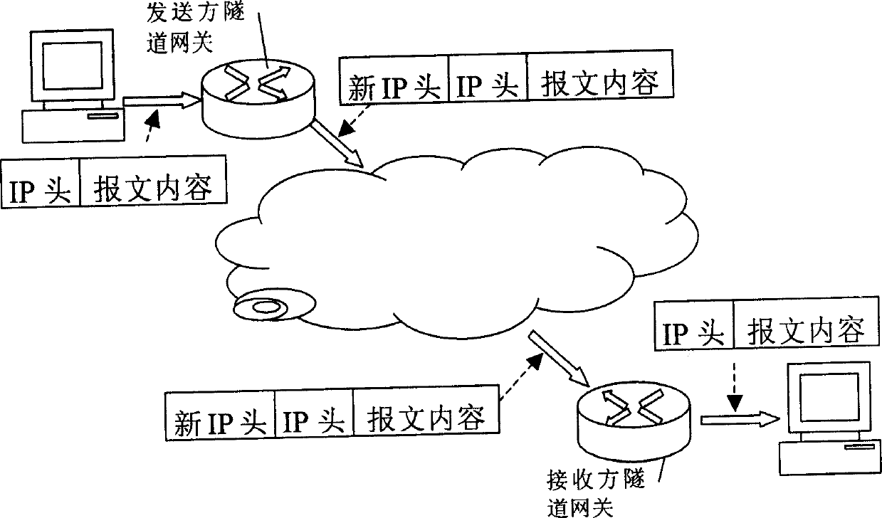
[0159] Including: source node 121, sender tunnel gateway 122, receiver tunnel gateway 123, destination node 124, node link between source node 121 and sender tunnel gateway 122, receiver tunnel gateway 123 and destination node 124 The node link of the sender tunnel gateway 122 and the tunnel link between the receiver tunnel gateway 123 .
[0160] The sender gateway 122 includes: a tunnel link MTU acquiring means 125 for acquiring the tunnel link MTU, and a tunnel link MTU configuring means 126 for configuring the acquired tunnel link MTU.
[0161] When the tunnel link of the sending side and the tunnel link of the receiving side are established, the MTU value of the tunnel link is obtained by the tunnel link MTU obtaining means 125, and then the value is configured to the sending side tunnel by the tunnel link MTU configuring means 126. on the exit of the gateway.
[01...
no. 2 example
[0163] Fig. 13 is the networking diagram of the second embodiment of the system of the present invention:
[0164] Wherein, the source node 121 includes:
[0165] The path MTU detection message setting device 127 is used to set the required message for detecting the path MTU;
[0166] Probing message length adjusting device 128, configured to adjust the length of the path MTU probing message;
[0167] The path MTU discovery unit 129 is configured to discover the path MTU according to the path MTU detection message.
[0168] When the source node needs to detect the path MTU, at first the detection message is constructed by the path MTU detection message setting device 127, and the DF bit in the message header field is set to be 1, indicating that the message cannot be fragmented, and the length of the message is set to be greater than that of the source node. The MTU value of the node host exit, and encapsulate the ICMP error control message into the message, so that the rece...
no. 3 example
[0169] Fig. 14 is the network diagram of the third embodiment of the system of the present invention:
[0170] Among them, two tunnels are built on the tunnel gateway at the sender side: tunnel 1 and tunnel 2. Logical interface 223 is built corresponding to tunnel 1, and logical interface 224 is built corresponding to tunnel 2. The link MTU of tunnel 1 is configured in On logical interface 223 , the link MTU of tunnel 2 is configured on logical interface 224 .
[0171] The logical interface 223 and the logical interface 224 are respectively coupled to the node link interface 221 and the tunnel link interface 222 . The node link interface 221 is used for communicating with the adjacent nodes connected through the node link; the tunnel link interface 222 is used for communicating with the adjacent nodes connected through the tunnel link.
[0172] After the source node sends a non-fragmentable path MTU detection message (IP message) to the tunnel gateway of the sender through th...
PUM
 Abstract
Description
Claims
Application Information
 - R&D
- Intellectual Property
- Life Sciences
- Materials
- Tech Scout
- Unparalleled Data Quality
- Higher Quality Content
- 60% Fewer Hallucinations
Browse by: Latest US Patents, China's latest patents, Technical Efficacy Thesaurus, Application Domain, Technology Topic, Popular Technical Reports.
© 2025 PatSnap. All rights reserved.Legal|Privacy policy|Modern Slavery Act Transparency Statement|Sitemap|About US| Contact US: help@patsnap.com


