Wavelet changeable VLSI structure based on line

A wavelet transform and line transform technology, applied in television, electrical components, digital video signal modification and other directions, can solve problems such as low utilization of hardware resources and large storage space, to ensure real-time processing, reduce storage space requirements, save The effect of processing time

Inactive Publication Date: 2006-01-04
XIDIAN UNIV
View PDF0 Cites 15 Cited by
  • Summary
  • Abstract
  • Description
  • Claims
  • Application Information

AI Technical Summary

Problems solved by technology

[0011] The purpose of the present invention is to provide a VLSI structure based on row-based wavelet transform, to overcome the problems of low hardware resource uti...

Method used


Image

  • Wavelet changeable VLSI structure based on line
  • Wavelet changeable VLSI structure based on line
  • Wavelet changeable VLSI structure based on line

Examples


Embodiment Construction

[0031]This embodiment adopts 9 / 7 wavelet as the wavelet base, uses XILINX ISE 5.1 ​​integrated development software and VHDL, Verilog HDL language, and completes 4-level line-based wavelet transform on XC2V3000-6BG728 programmable chip of XILINX company.

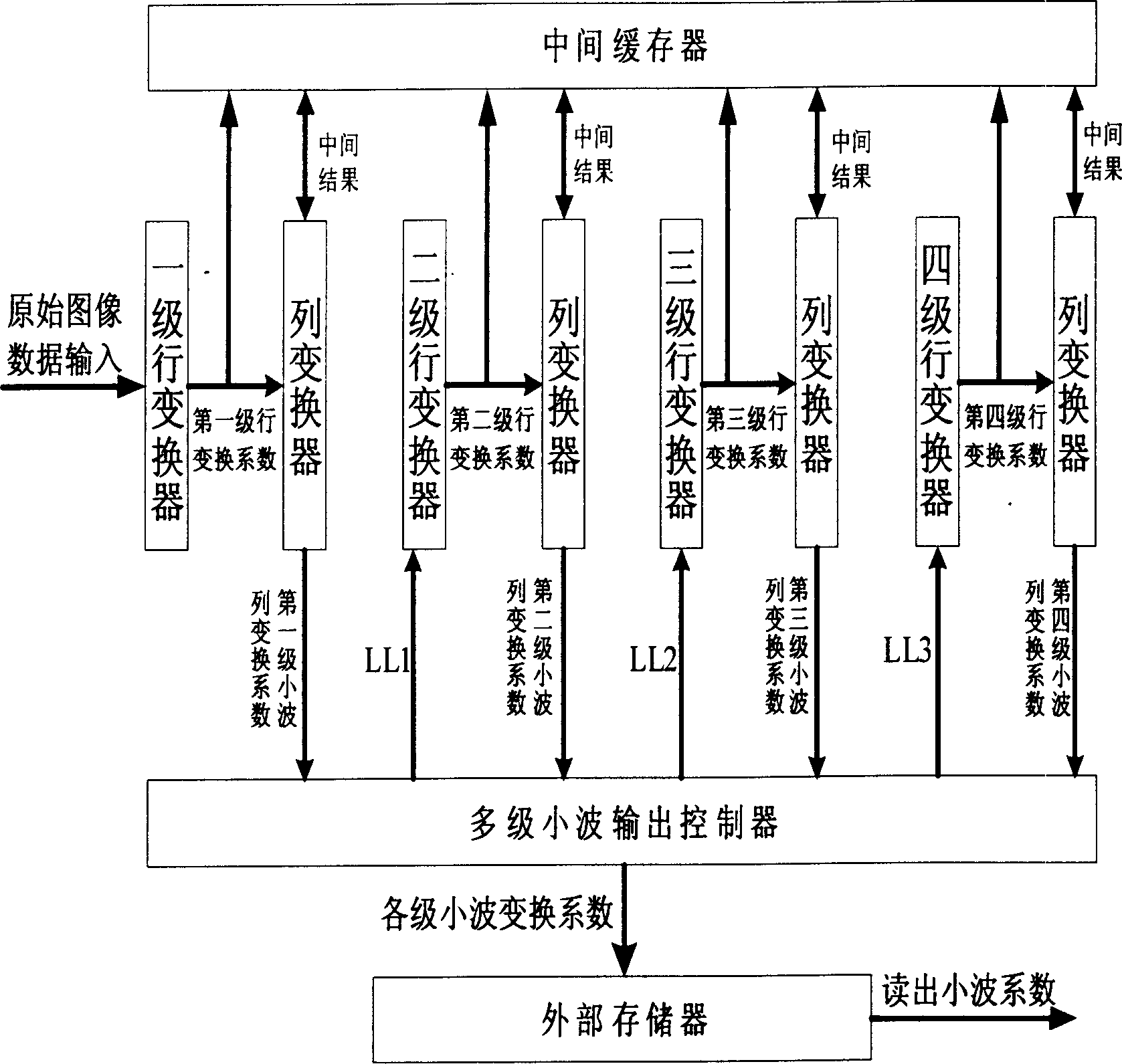
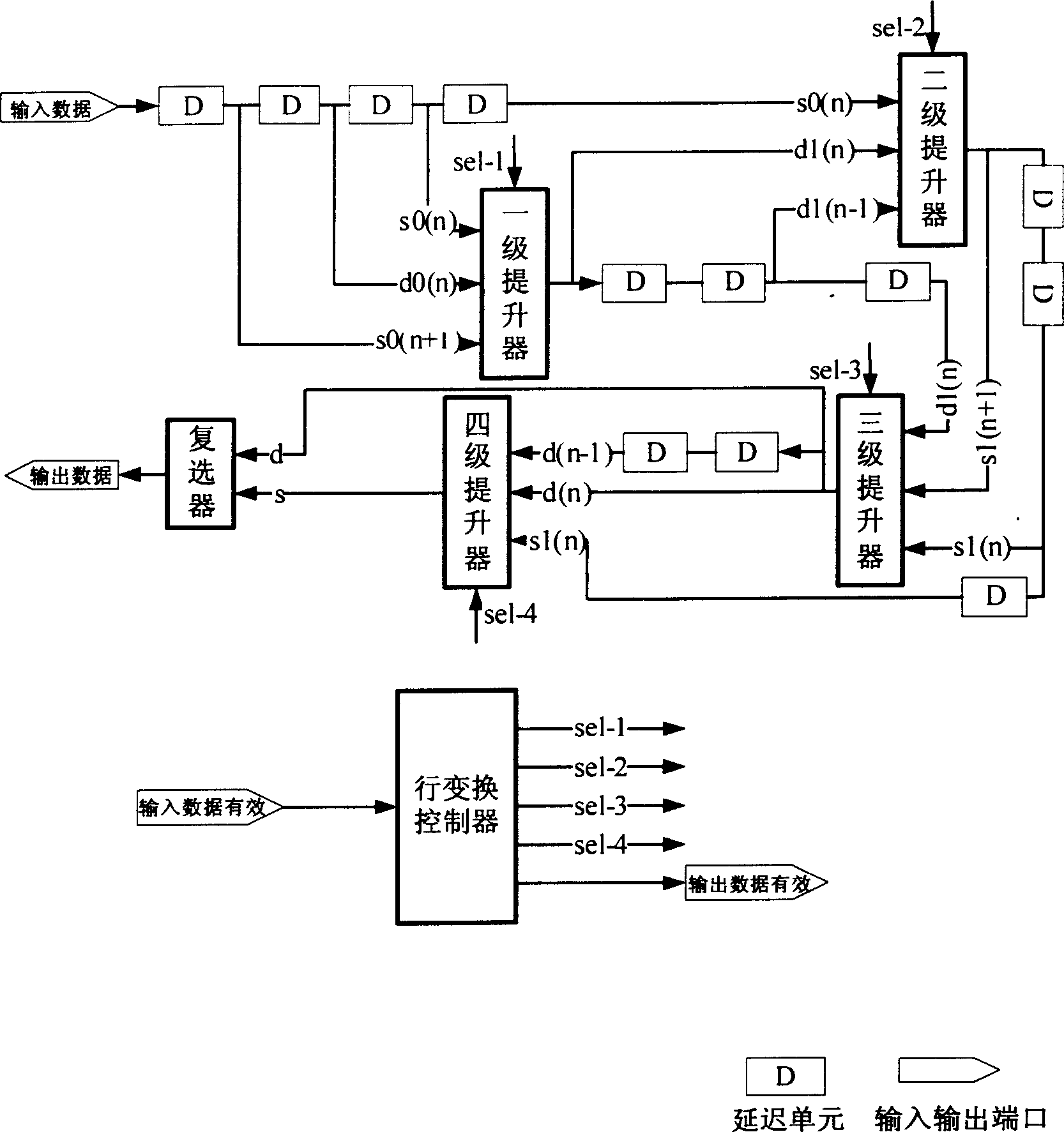
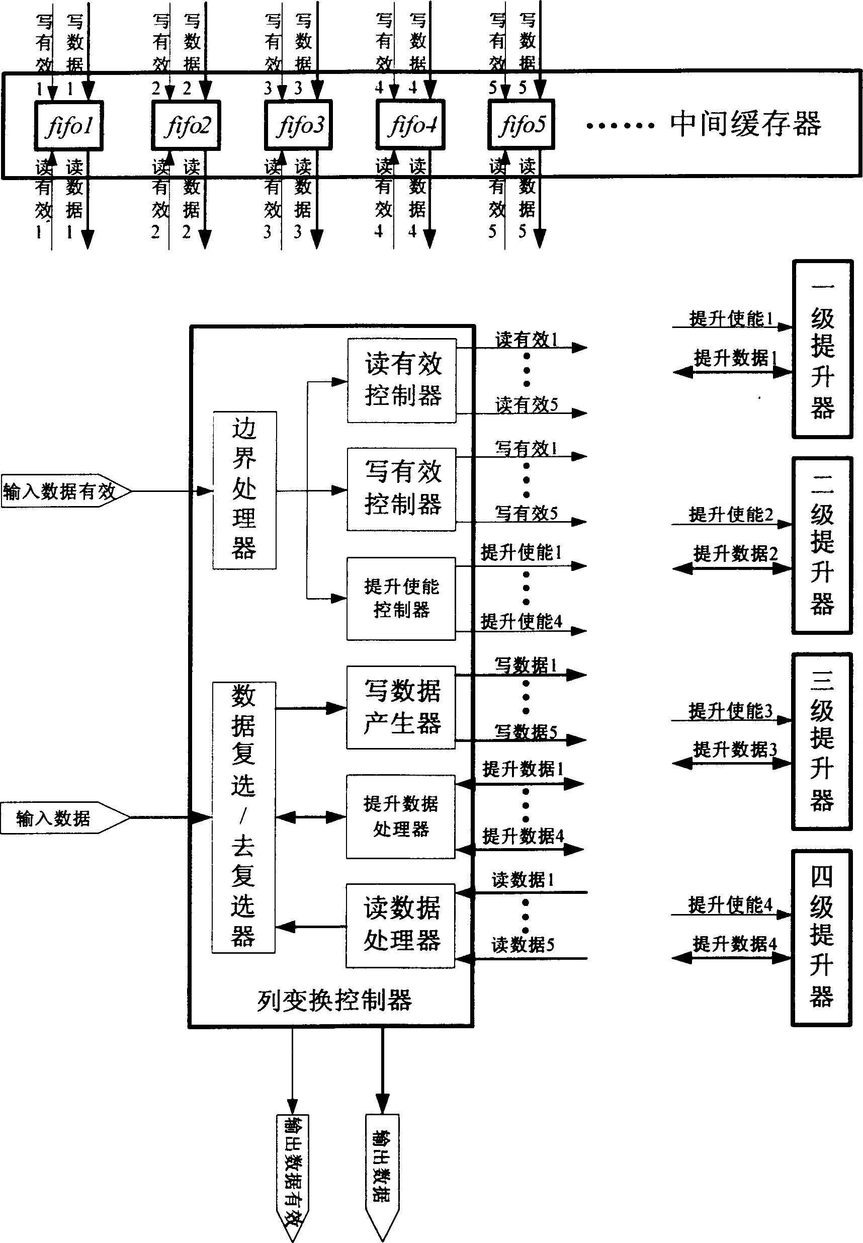
[0032] see figure 1 , the structural block diagram of this embodiment includes a row converter, a second row converter, a third row converter, a fourth row converter, a column converter, an intermediate buffer, a multi-stage wavelet coefficient output controller and an external memory . The first-level line converter first performs the first-level wavelet line transform on the input original image data, and the first-level line transform coefficients obtained by the transformation are divided into two outputs, one is input to the intermediate buffer to cache the required intermediate data, and the other is All the way to the column converter. The column converter is bidirectionally connected to the intermediate buffer, an...


PUM


Abstract

This invention discloses a super large scale IC VLSL structure of a small wave transformation based on lines including a first stage line transformer, a column transformer, a middle buffer, a multiple-stage small wave factor output controller and an external storage, among which, said first stage line transformer carries out small transformation of a first line direction, the second and above the second stage line transformers carry out line direction small wave transformation to the first stage small wave transformed low frequency sub-band system and writes the result into the middle buffer, a column transformer fetches the data of the buffer to finish the column direction small wave transformation and outputs the result to the multiple-stage factor output the result to the multiple-stage factor output controller, which re-selects and buffer stores the column transformed factors of each stage and the sub-band factors of each stage are output to the next stage line transformer, the rest factors are output to the external storage.

Description

Technical field: [0001] The invention relates to the field of image compression coding, in particular to a very large scale integrated circuit (VLSI) structure based on row wavelet transform, which is used for various digital image coding. technical background: [0002] With the development and application of multimedia and network technology, people's demand for image information is increasing day by day. The huge amount of data contained in the image has caused great pressure and difficulties on the transmission channel and storage medium with a certain capacity. Therefore, it is necessary to use image compression coding technology to compress the image efficiently to meet the requirements of real-time transmission and efficient storage. Previous image coding methods mainly include entropy coding, differential pulse code modulation (DPCM), compression methods based on discrete cosine transform DCT, etc., especially DCT-based compression coding methods have formed internati...

Claims


Application Information

Patent Timeline
IPC IPC(8): H04N7/26H04N19/426H04N19/63
Inventor 李云松刘凯王柯俨吴成柯曹斌
Owner XIDIAN UNIV
Why Eureka
Try Eureka