Air inlet structure for engine

A technology of air intake structure and engine, which is applied in the field of vehicles, can solve problems such as the smaller configuration space of air intake system components, the inability to arrange resonators and throttle bodies close to each other, and achieve the effect of expanding the installation and placement space

Inactive Publication Date: 2006-01-11
SUZUKI MOTOR CORP
View PDF2 Cites 7 Cited by
  • Summary
  • Abstract
  • Description
  • Claims
  • Application Information

AI Technical Summary

Problems solved by technology

[0006] However, in the case of disposing the air filter above the engine, since the resonator and the air filter tend to be larger in recent years, it is impossible to arrange the resonator and the throttle body adjacently on the top of the engine, thereby causing air intake The problem that the configuration space of system components becomes smaller

Method used


Image

  • Air inlet structure for engine
  • Air inlet structure for engine
  • Air inlet structure for engine

Examples


Embodiment 1

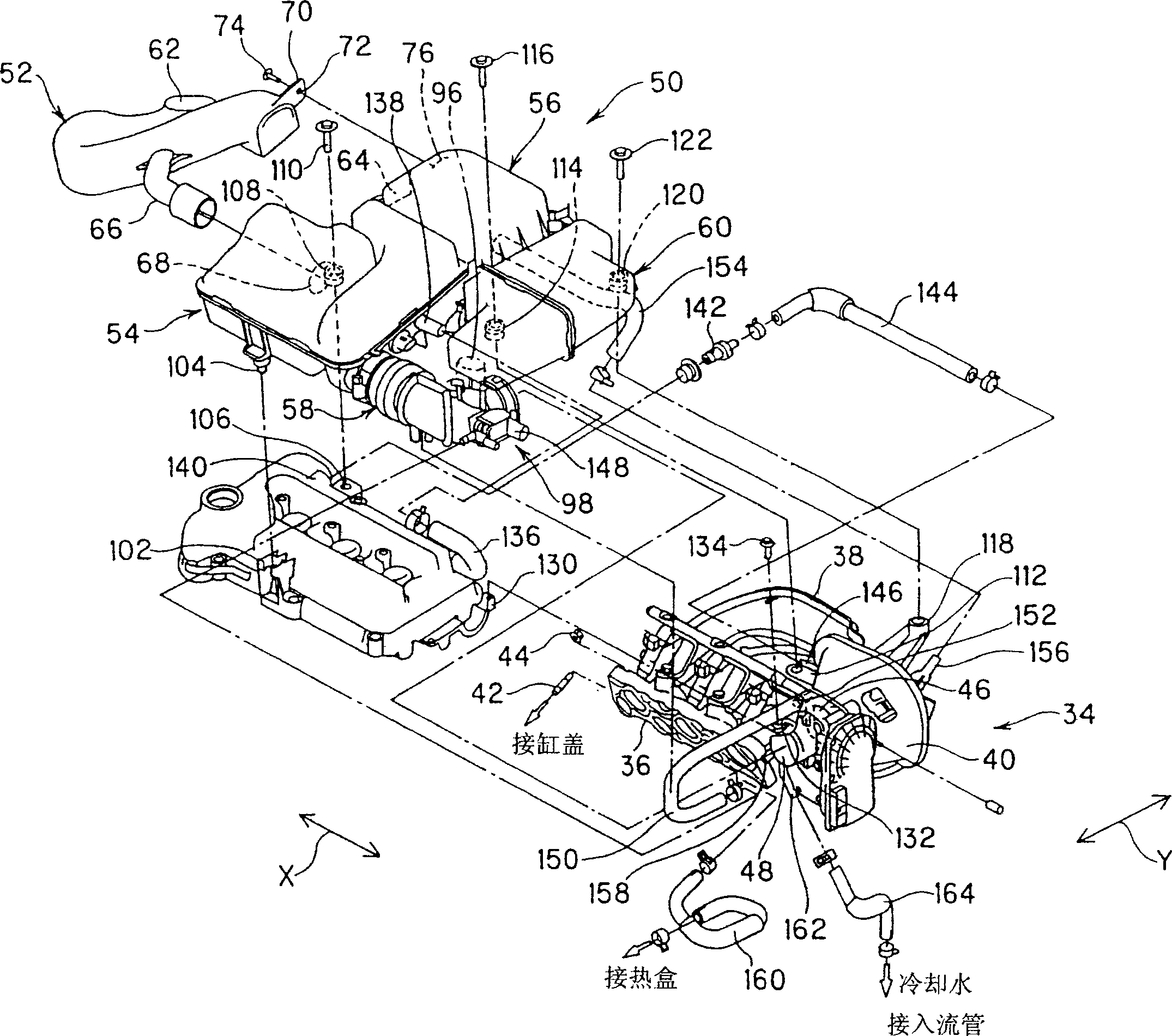
[0022] Example 1: Figure 1-Figure 8 Shows the first embodiment of the present invention. exist Figure 6-Figure 8 In the engine room (not shown) of the vehicle, a multi-cylinder (3-cylinder) engine 2 installed side by side is located at the lower part of the engine 2 and is connected to a gearbox 4 installed on the left side of the engine 2 . The engine 2 and the transmission 4 are mounted on the vehicle in the longitudinal direction of the crankshaft, that is, in the lateral direction X of the vehicle (the left-right direction of the vehicle).

[0023] The engine 2 is provided with a lower cylinder block 6 , an upper cylinder head 8 , an oil pan 10 attached to the lower portion of the cylinder block 6 , and a cylinder head 12 attached to the upper portion of the cylinder head 8 .

[0024] On the cylinder block 6, a water pump 16 and an alternator 18 are installed on the right side of the vehicle while being supported by the crankshaft 14 in the lateral direction X of the v...

Embodiment 2

[0068] Example 2: Figure 9 It is a special structure of the present invention and shows the second embodiment.

[0069] In this second embodiment, parts having the same functions as those in the above-mentioned first embodiment are denoted and described with the same symbols.

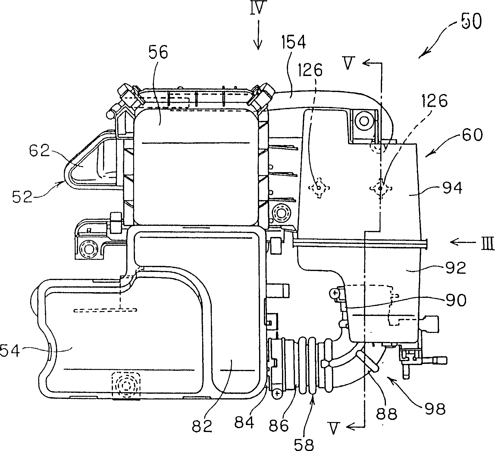
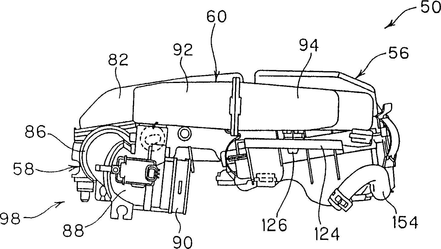
[0070] The characteristic points of this second embodiment are as follows. That is, the downstream side resonator 60 is composed of a front box 92 and a rear box 94, and the required capacity is set, and the front box 92 and the rear box 94 can slide relative to each other, for example, the rear box 94 can This rear case 94 is fixed at a predetermined position by a fixing means (not shown) by sliding with respect to the front case 92 .

[0071] According to this second embodiment, for example, the design status of the vehicle, such as in the case of a low chassis or a high chassis, the rear side box 94 is slid so that the downstream side resonator 60 can be adapted to the capacity required for the lo...


PUM


Abstract

The invention relates to an air-intake structure for an engine. An air filter is arranged above the engine at the same time of arranging a gear box at one side of the engine. A downstream air-intake channel is arranged between the air filter and an air-intake manifold. A resonator is arranged on the downstream side intake channel. The air filter and the resonator are supported by the engine. The upstream side of the intake manifold is extended outwardly from one side face of the engine. The downstream side intake passage is arranged on the upper face of the gear box, and the resonator is arranged on the upper face of the downstream side intake channel. The beneficial effect of the invention is that the mounting and putting space of the components of the air-intake system, such as the air filter positioned on the engine are expanded; and large-scale air filters and resonators can be arranged on the engine.

Description

Technical field [0001] The invention relates to an air intake structure of an engine, especially related to the air intake structure for enlarging the arrangement space of air intake system components, and belongs to the technical field of vehicles. Background technique [0002] On the engine of the vehicle, as an intake system component, there is an intake manifold having a pressure equalization tank, and a resonator and an air filter are installed on the upstream side of the intake manifold. [0003] In the past, in the air intake structure of the engine, there are precedents in which the pressure equalization box is arranged at the rear of the engine, the air filter is arranged on the side of the engine, and the resonator is adjacent to the pressure equalization box and the air filter. [0004] In addition, in the intake structure of the engine, while the intake pipe with the expansion and contraction part is connected to the air filter and the throttle body, there is a p...

Claims


Application Information

Patent Timeline
Patent Type & Authority Applications(China)
IPC IPC(8): F02M35/10F02B29/04F02B67/00F02M35/04
CPCY02T10/146Y02T10/12
Inventor 津田卓嗣
Owner SUZUKI MOTOR CORP
Why Eureka
Try Eureka