Pipe heat exchanger

A tubular heat exchanger and heat exchanger technology, applied in the field of heat exchange devices, can solve the problems of reduced heat transfer coefficient, increased use cost, hindering heat exchange between high-temperature fluid and low-temperature fluid, etc., to improve heat transfer coefficient, The effect is good and the production cost is saved

Inactive Publication Date: 2006-01-11
刘庆久
View PDF0 Cites 21 Cited by
  • Summary
  • Abstract
  • Description
  • Claims
  • Application Information

AI Technical Summary

Problems solved by technology

However, because the high-temperature fluid is usually oil or gas, and the oil fluid has a certain viscosity, when it moves along the swirl plate at a slow speed in the shell, it is easy to cause the outer wall of the heat exchange tube to form Relatively thick oil film, which can hinder heat exchange between high temperature fluid and low temperature fluid
It can be seen that the heat transfer coefficient of the shell-and-tub

Method used


Image

  • Pipe heat exchanger
  • Pipe heat exchanger

Examples


Embodiment Construction

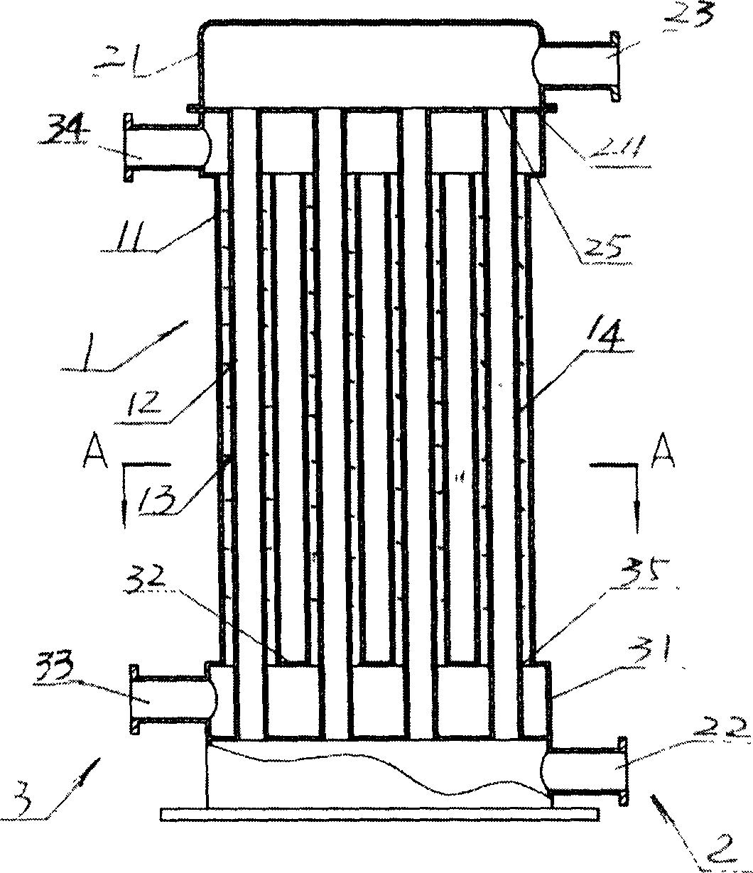
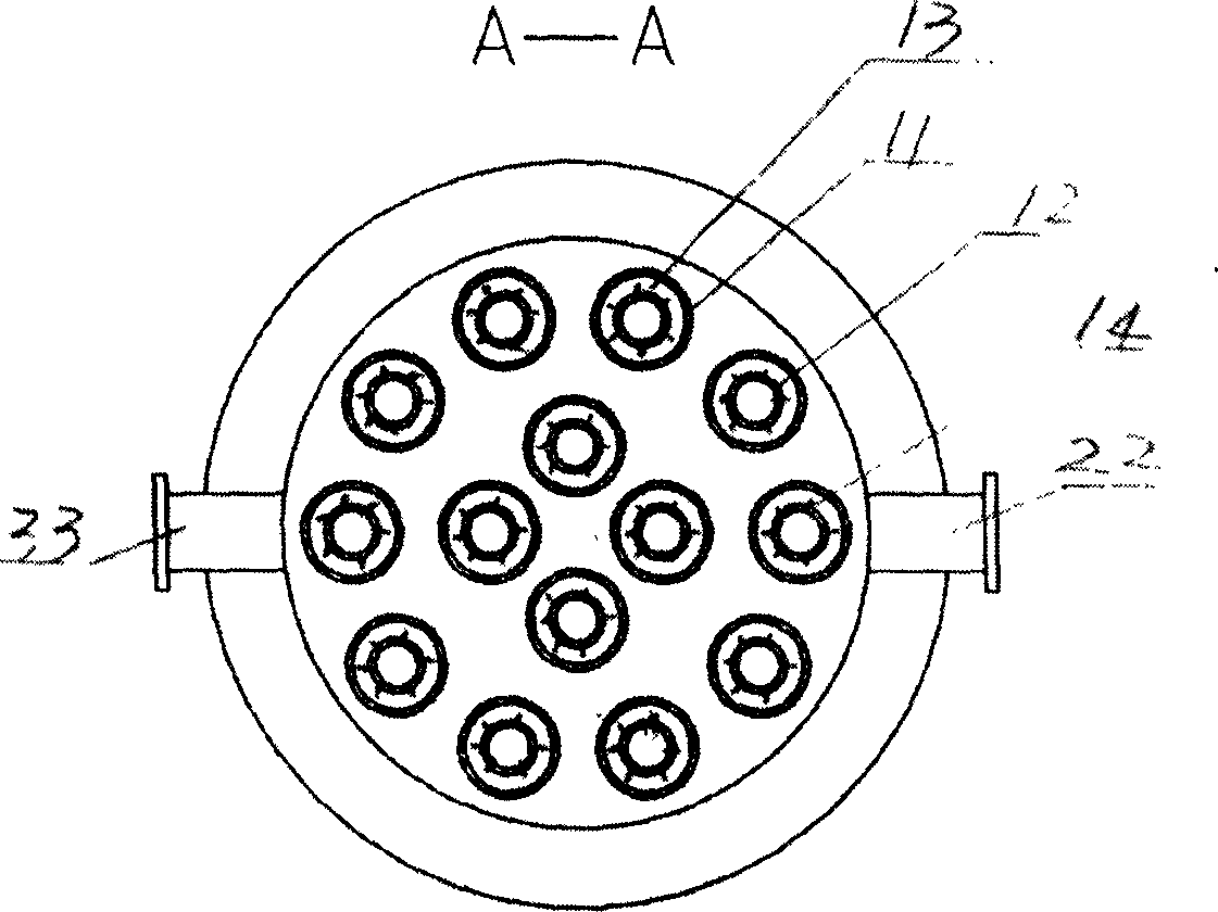
[0010] See attached figure 1 And attached figure 2 , these two drawings show the overall structure of the appearance of an embodiment of the tube heat exchanger proposed by the present invention. As can be seen from the accompanying drawings, the heat exchanger includes two parts: the casing group 1 and the header group.

[0011] The sleeve group 1 is a sleeve bundle composed of multiple sleeves, each of which has an outer tube 11 and an inner tube 12 inserted into the outer tube 11 and provided with rows of protrusions 14 around its periphery, The protrusion 14 can increase the heat dissipation area of ​​the inner tube 12 , both ends of the inner tube 12 extend beyond the two ends of the outer tube 11 , and there is a certain distance 13 between the outer wall of the inner tube 12 and the inner wall of the outer tube 11 . When the high-temperature fluid is oil, the distance 13 can be designed to be relatively small, and when the high-temperature fluid is gas, the distance ...


PUM


Abstract

The present invention relates to a pipe-type heat exchanger. Said heat exchanger includes two portions of pipe sleeve group and pipe header group including first pipe header for making first medium circularly flow and second pipe header for making second medium circularly flow. Said invention can make the fluid be quickly flowed in the pipe sleeve so as to can obtain higher heat exchange coefficient.

Description

Technical field: [0001] The invention relates to a device for heat exchange between two fluids of high temperature and low temperature, specifically a tube heat exchanger. Background technique: [0002] Shell and tube heat exchangers are commonly used in the prior art. The heat exchanger has a shell that allows high-temperature fluid to pass through. The upper and lower ends of the shell are respectively provided with inlets or outlets for the high-temperature fluid to enter and flow out, and many tubes arranged in a predetermined manner are installed in the shell. The heat exchange tubes and / or the swirl plates installed in a spiral manner around the heat exchange tubes from top to bottom, and another low-temperature fluid can circulate in the heat exchange tubes to cool down the high-temperature fluid circulating outside the heat exchange tubes. Because the shell-and-tube heat exchanger can easily realize heat exchange during the circulation of two different temperature f...

Claims


Application Information

Patent Timeline
IPC IPC(8): F28D7/10
Inventor 刘庆久温洪波
Owner 刘庆久
Why Eureka
Try Eureka