Method for correcting power

A technology of power calibration and power compensation, applied in the field of wireless communication, can solve the problem of high cost, achieve the effect of reducing requirements and avoiding cost increase

Inactive Publication Date: 2006-01-11
STATE GRID JIANGXI ELECTRIC POWER CO +1
View PDF0 Cites 22 Cited by
  • Summary
  • Abstract
  • Description
  • Claims
  • Application Information

AI Technical Summary

Problems solved by technology

Doing so

Method used


Image

  • Method for correcting power
  • Method for correcting power
  • Method for correcting power

Examples


Embodiment Construction

[0035] The power compensation method of the present invention is divided into two links of off-line calibration and on-line compensation.

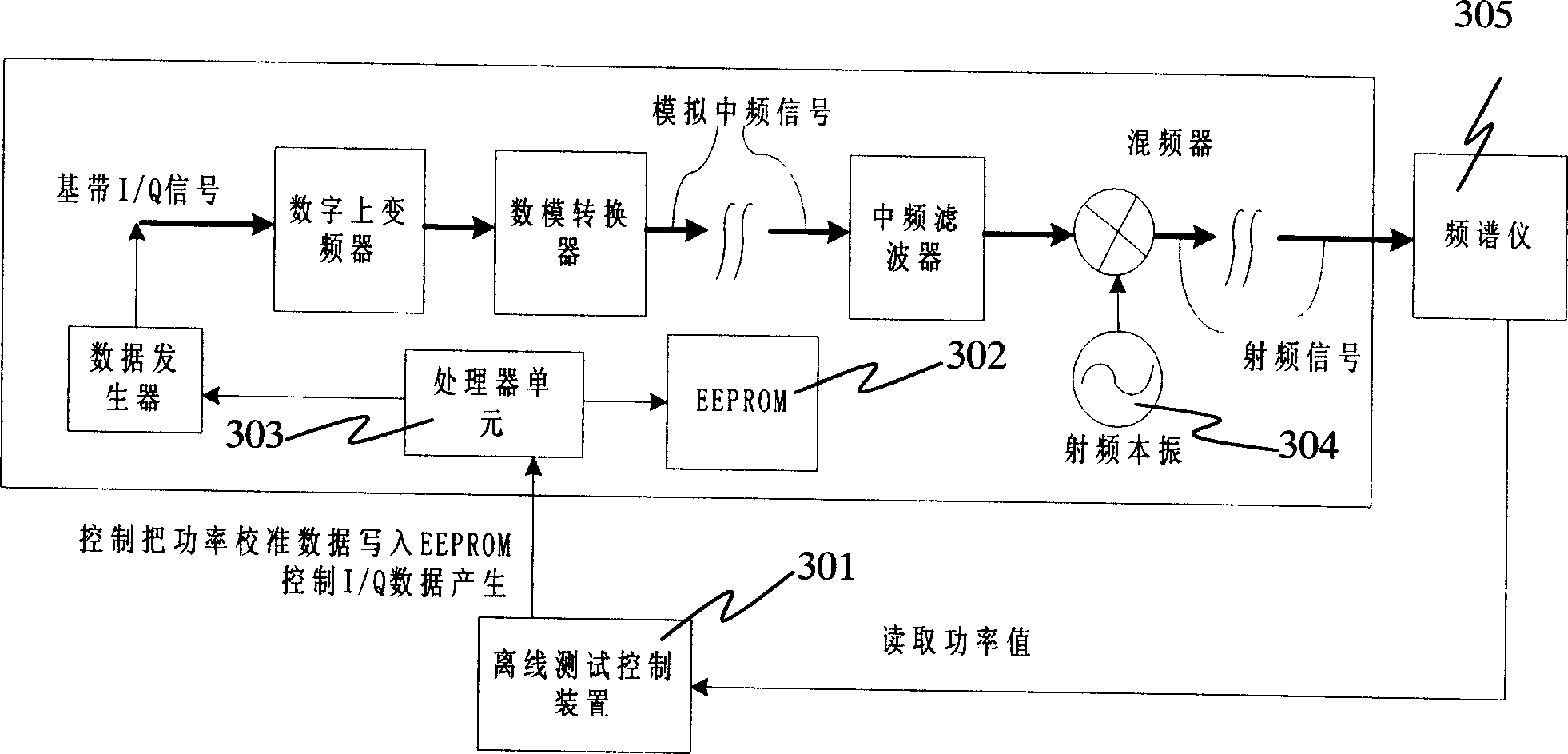
[0036] Off-line calibration means that the transmitter works in the off-line calibration mode, transmits a specific carrier signal, measures the power compensation values ​​corresponding to different intermediate frequency and radio frequency points and stores them in EEPROM 302 (electrically erasable read-only memory). The block diagram of offline calibration is as follows image 3 As shown, because only one carrier is used in offline calibration, so in image 3 Only the processing of carriers is shown in . The specific steps of offline calibration are as follows:

[0037] Step 1: Divide the intermediate frequency into multiple small frequency bands, and the center frequency of each frequency band is used as the intermediate frequency point.

[0038] Step Two: Pass image 3 The offline test control device 301 in the control transmitte...


PUM


Abstract

This invention relates to a power correction method including a step of off-line calibration: setting a sender at the off-line calibration mode controlling the sender to emit a specific carrier signal, measuring and storing IF spot power compensating value and/or RF spots power compensation value corresponding to different IF and/or RF spots of the carrier, an on-line compensation step: setting said sender at normal operation mode to take out the stored related power compensating values of IF spots and/or RF spots to compensate the output power of said carrier, which can compensate the power difference resulted by IF spots of multiple carriers to reduce requirement on IF filter pass-band flatness of IF filter.

Description

technical field [0001] The invention relates to a method for calibrating the power of a transmitter, in particular to calibrating the power of a multi-carrier base station or a mobile terminal in the field of wireless communication. Background technique [0002] Such as figure 1 As shown, the general transmitters use the baseband signal to be mixed to the intermediate frequency, and then the intermediate frequency is mixed to the radio frequency output. The intermediate frequency output generally needs to be processed by the intermediate frequency filter 101 . When the frequency of the RF output changes within the entire frequency band designed by the transmitter, if the baseband in-phase component / quadrature component (I / Q) signal and related control signals (such as the control of the variable gain amplifier of the transmission channel, etc.) changes, the power of the RF output will vary with frequency. In order to stabilize the output power, it is necessary to compensa...

Claims


Application Information

Patent Timeline
IPC IPC(8): H04B1/04
Inventor 王志刚陶俊
Owner STATE GRID JIANGXI ELECTRIC POWER CO
Why Eureka
Try Eureka