LED lighting lamp and its manufacturing method

A technology of LED lighting and manufacturing method, which is applied in the field of lighting, can solve problems such as powerlessness and LED damage, and achieve the effects of saving man-hours, sufficient contact, and reduced selection conditions

Inactive Publication Date: 2006-01-25
连伟 +1
View PDF2 Cites 9 Cited by
  • Summary
  • Abstract
  • Description
  • Claims
  • Application Information

AI Technical Summary

Problems solved by technology

[0004] In addition, since the distance between the solder joint and the LED lamp body is very close during welding, generally 2 to 5 mm, there are strict restrictions on the welding time and temperature, otherwise the LED may be damaged. When using LED lighting fixtures, this method seems powerless

Method used


Image

  • LED lighting lamp and its manufacturing method
  • LED lighting lamp and its manufacturing method

Examples


Embodiment Construction

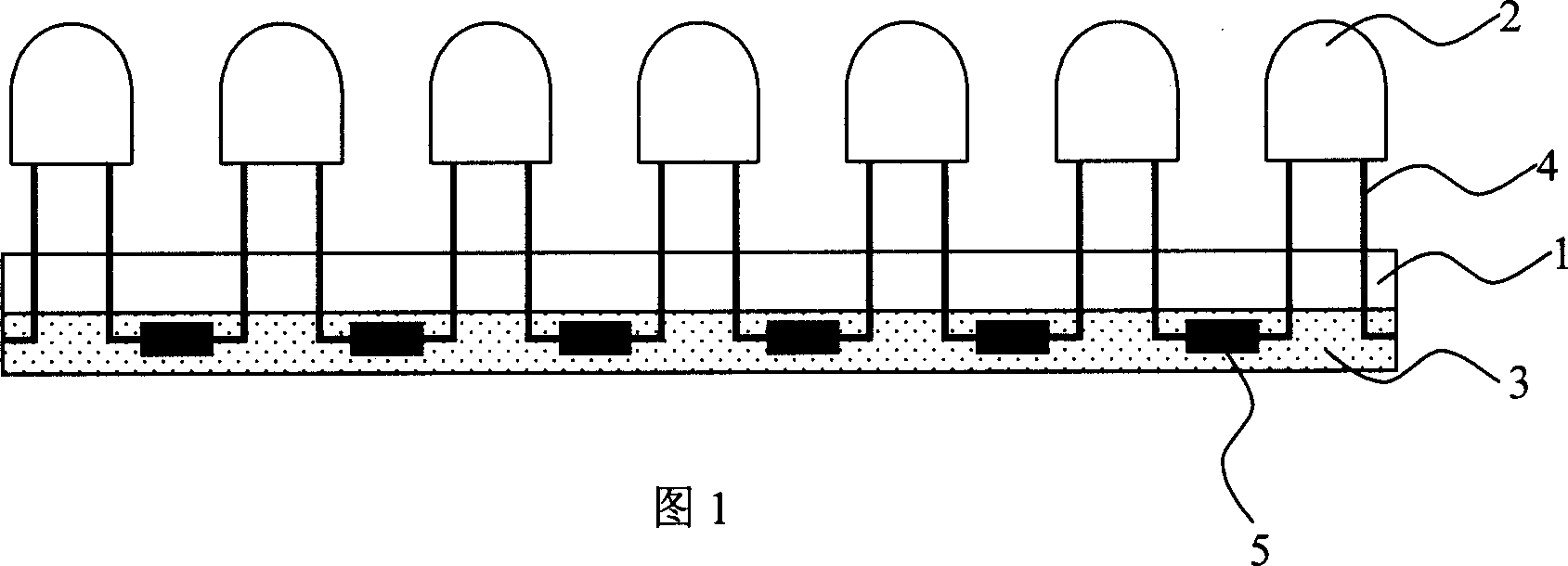
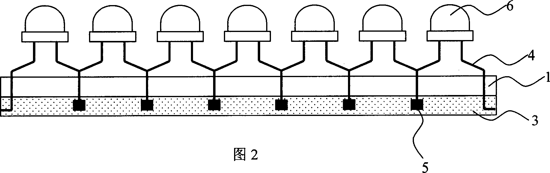
[0019] The invention provides an LED lighting fixture, which uses several LED lamps as light sources. The pins of these LED lamps pass through an insulating substrate and are connected to each other on the back of the insulating substrate according to a predetermined circuit structure. The LED lamps used in the present invention can be 2-pin LEDs such as various cylindrical, conical, and straw hat-shaped LEDs, or piranha LEDs, and multi-pin special-shaped LEDs. Based on the above structure, theoretically speaking, there is no special requirement for the insulating substrate, and any solid insulating material can be used, such as glass plate, PCB board, plastic plate, etc. In the present invention, ceramic plates with low price and good insulating effect are preferred, especially It is currently the most popular ultra-thin ceramic plate for research and development. Its material is thin (up to about 3mm), high strength, light weight, smooth and delicate surface, which is conduc...


PUM


Abstract

The invention discloses a LED exciter lamp, comprising an insulating substrate, several LED lamps and thermal a conductive packaging layer, where the pins of the LED pass through the insulating substrate and are connected in a designed circuit structure, and the thermal conductive packaging layer seals the said pins at the back of the insulating substrate. It provides a method for manufacturing the LED exciter lamp. Its advantages lie in that: directly using the pins of the LED for connection, convenient and saving materials; besides, allowing high density LED mounting, beneficial to raising the unit area light intensity of the exciter lamp.

Description

【Technical field】 [0001] The invention relates to lighting technology, in particular to an LED lighting fixture and a manufacturing method thereof. 【Background technique】 [0002] LED, that is, light-emitting diode, has been widely used in various occasions such as landscape lighting and large-screen display due to the rapid development of main technical indicators such as brightness in recent years, and will enter the field of general lighting on a large scale. In the process of energizing and emitting light, LED will generate a lot of heat. These heats are very harmful to LED devices, and the generated heat must be dissipated by appropriate means to ensure that the LEDs work within an appropriate temperature range. Commonly used LED devices have various packaging forms, such as: cylindrical, conical, straw hat and other 2-pin LEDs, piranha LEDs, SMD LEDs, and multi-pin special-shaped LEDs, etc. Manufacturers have taken heat dissipation into consideration when designing a...

Claims


Application Information

Patent Timeline
Patent Type & Authority Applications(China)
IPC IPC(8): F21S4/00F21V19/00F21V29/00F21W131/00F21Y101/02F21V29/85F21Y115/10
Inventor 吕大明连伟
Owner 连伟
Why Eureka
Try Eureka