
Wound-rotor type transformer and power source utilizing wound-rotor type transformer

A power supply device and transformer technology, applied in the direction of transformer/inductor coil/winding/connection, electric light source, lighting device, etc., can solve the problems of increasing insulation distance and insufficient safety, and achieve the effect of improving insulation

Inactive Publication Date: 2006-01-25
河野 和夫
View PDF0 Cites 2 Cited by
  • Summary
  • Abstract
  • Description
  • Claims
  • Application Information

AI Technical Summary

Problems solved by technology

In order to increase the distance between the secondary output terminal connected to the high voltage side of one end of the secondary winding and the lead wire connected to it, and the secondary output terminal connected to the high voltage side of the other end of the secondary winding and the lead wire connected to it Insulation distance, although insulating grooves can be provided on the printed circuit board to form an air gap between the secondary output terminals, etc., but it may cause discharge between the secondary output terminals, and leakage current occurs between the two, resulting in high-voltage current Flow to the printed substrate, there is a problem of insufficient safety

Method used


Image

  • Wound-rotor type transformer and power source utilizing wound-rotor type transformer
  • Wound-rotor type transformer and power source utilizing wound-rotor type transformer
  • Wound-rotor type transformer and power source utilizing wound-rotor type transformer

Examples


Embodiment Construction

[0106] Hereinafter, embodiments of the present invention will be described in detail with reference to the accompanying drawings.

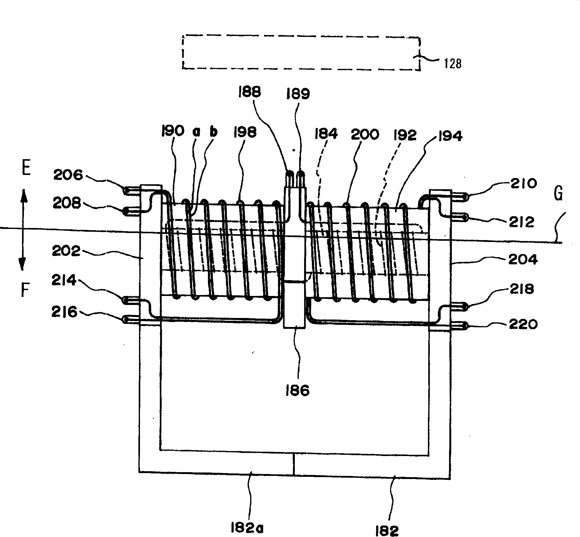
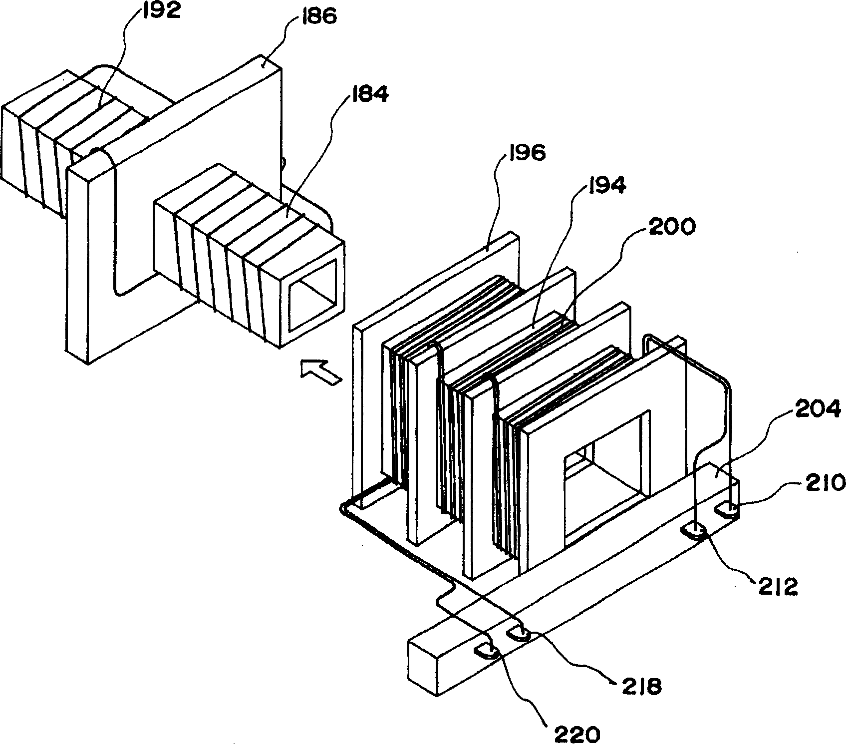
[0107] In Fig. 1, 182 is an iron core, and two iron cores in [shape and] shape are joined to form a quadrangular frame-shaped iron core. The primary bobbin 184 is inserted into one of the parallel portions of the iron core 182 . The terminal base 186 is fixed at the center of the primary bobbin 184 , and the primary output terminals 188 and 190 are set on the terminal base 186 . The primary winding 192 is mounted on the aforementioned bobbin 184, and both ends of the primary winding 192 are connected to the primary output terminals 188 and 190 via lead wires.

[0108] A pair of secondary bobbins 191 and 194 are inserted and arranged on the outside of the aforementioned primary bobbin 184 and on both sides of the terminal block 186 . The partitions 196 at each end of the secondary bobbins 191 and 194 are in contact with both side surfaces of the ...


PUM


Abstract

An object of this invention is to enhance insulating properties between the terminals provided at both terminals of the secondary windings of the wound-rotor type transformer, and to drive the wound-rotor transformer safely, and the primary windings 110, secondary windings M1, M2 are mounted on the bobbins inserted with the bobbins. The terminal base 1 is provided at the side where the high tension terminals of the bobbins 102, 104 are disposed, and The first terminals S1, S2, S3 and S4 connected to the one terminals of the primary windings M1, M2 are mounted on the terminal base 1 at the side where the high tension terminals are disposed. The second terminals A, B connected to the other terminals of the secondary windings M1, M2 mounted on the bobbins 102, 104 are mounted at the side where the rearward low tension terminals are disposed at the side where the high tension terminals of the bobbins 102, 104 at a predetermined distance. The second terminals A, B are used as the ground terminals.

Description

technical field [0001] The present invention relates to a winding-type transformer for driving a lamp such as a cold-cathode fluorescent lamp, etc., and a power supply device using the winding-type transformer. Background technique [0002] Winding-type transformers used for driving circuits of discharge lamps, etc., are generally as shown in Fig. 18. Through the winding frame (not shown), the primary winding P and the secondary winding S are installed on the iron core C, and the transformer is installed. The input side terminal block is provided with primary input terminals T1 and T2 connected to the primary winding P, and the output side terminal block is provided with secondary input terminals T3 and T4 connected to both ends of the secondary winding S. [0003] A winding-type transformer is provided on the printed circuit board, and when the winding-type transformer is used to drive a discharge type lamp such as a cold cathode fluorescent lamp, the winding-type transform...

Claims


Application Information

Patent Timeline
Patent Type & Authority Applications(China)
IPC IPC(8): H01F27/28H01F27/29H01F27/32H05B41/02
CPCY02B20/183
Inventor 河野和夫
Owner 河野 和夫
Learn More