Start-up circuit and method for controlling permanent magnet synchronous motor

A technology of permanent magnet synchronous motor and starting circuit, applied in the direction of starting device, etc., can solve the problems of high manufacturing cost, large harmonic interference, complex control algorithm, etc., and achieve the effect of reducing the cost of motor driving

Active Publication Date: 2011-08-03
GREE ELECTRIC APPLIANCES INC +2
View PDF6 Cites 2 Cited by
  • Summary
  • Abstract
  • Description
  • Claims
  • Application Information

AI Technical Summary

Problems solved by technology

At present, special frequency converters are required to drive permanent magnet synchronous motors. At present, AC-DC-AC frequency converters based on high-speed computing cores are commonly used. This frequency converter has the advantages of fast calculation speed and strong expansion functions. Disadvantages such as large wave interference and complicated control algorithm

Method used


Image

  • Start-up circuit and method for controlling permanent magnet synchronous motor
  • Start-up circuit and method for controlling permanent magnet synchronous motor
  • Start-up circuit and method for controlling permanent magnet synchronous motor

Examples


Embodiment 1

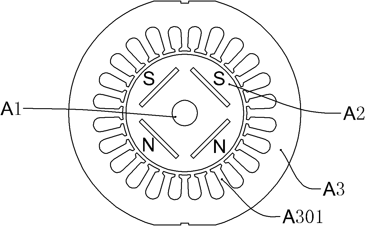
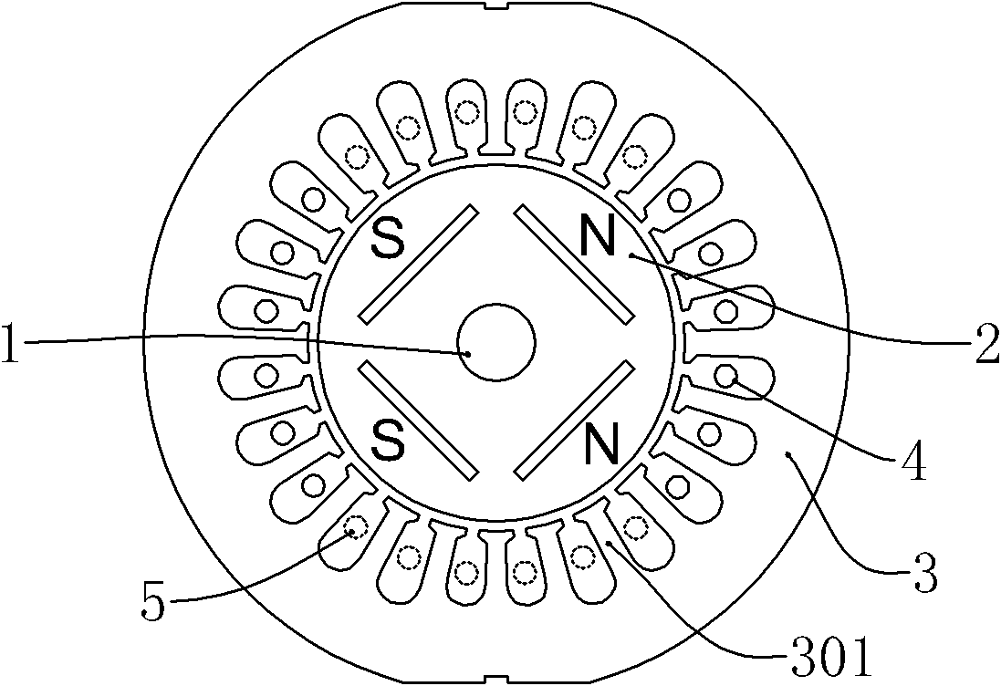
[0026] like figure 2 As shown, a single-phase permanent magnet synchronous motor includes a rotating shaft 1, a rotor 2, and a stator 3. The rotor 2 is sleeved on the rotating shaft 1, and the stator 3 is sleeved on the outside of the rotor 2; the rotor is a permanent magnet pole, and its There are two adjacently arranged S magnetic poles and two adjacently arranged N magnetic poles, and the two S magnetic poles are symmetrically distributed with the two N magnetic poles. Of course, three adjacently arranged S magnetic poles can also be arranged symmetrically. and three adjacently arranged N magnetic poles; the stator 3 is an inner-toothed salient pole core, with twenty-four salient pole core teeth 301; wherein, the main winding 4 and the auxiliary winding 5 have a spatial difference of 90 It is wound on the salient pole core teeth 301 of the stator in a degree manner.

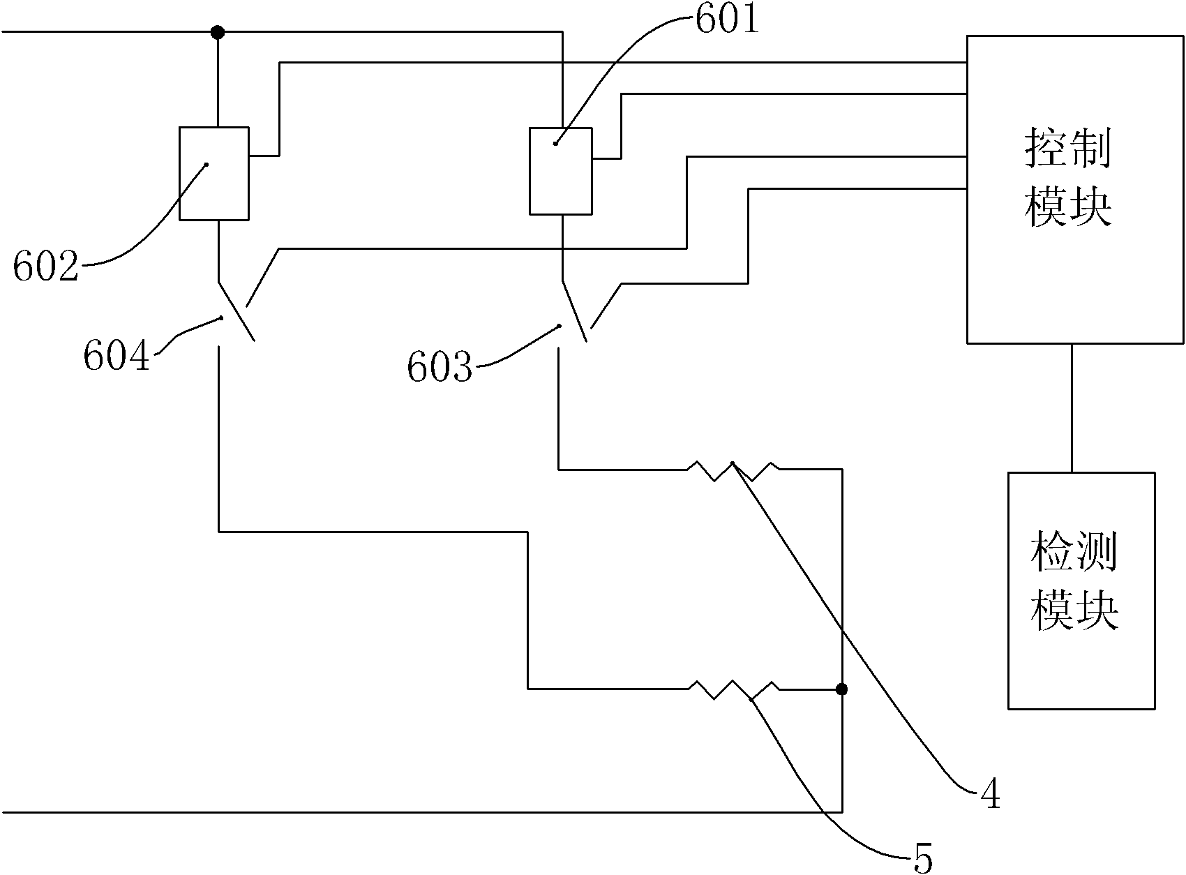
[0027] like image 3 As shown, a starting circuit for controlling the above-mentioned single-phase perma...

Embodiment 2

[0039] The difference from Embodiment 1 is that the permanent magnet synchronous motor is a three-phase permanent magnet synchronous motor, and the difference between the three-phase permanent magnet synchronous motor and the single-phase permanent magnet synchronous motor is that the number of windings of the rotor and the synchronous working power supply are different; Figure 8 As shown, a three-phase permanent magnet synchronous motor includes three windings: winding A, winding B and winding C, and winding A, winding B and winding C are wound in such a way that two adjacent windings differ in space by 60 degrees On the salient pole core teeth 301 of the stator 3 .

[0040] like Figure 9 As shown, a starting circuit for controlling the above-mentioned three-phase permanent magnet synchronous motor, the starting circuit includes an electronic switch A1 for converting alternating current into intermittent positive current or intermittent negative current, and an electronic s...


PUM


Abstract

The invention relates to a start-up circuit for controlling a permanent magnet synchronous motor. The permanent magnet synchronous motor comprises N windings. The start-up circuit comprises N windings, N electronic switches for converting an alternating current into an intermittent positive current or an intermittent negative current, a control module and a detection module used for detecting a rotor position and connected with the control module; the N windings are wound on and connected with a salient pole iron core tooth of a stator of the motor in a mode that every two adjacent windings are differed by 360 / 2N degrees on the space; the windings and the electric switches are serially connected to two ends of an alternating current power supply in a one-to-one correspondence manner; the control module is used for controlling the N electronic switches to work in turn according to the position of the rotor so that the N windings form a rotating magnetic field in a gap so as to drive the rotor to rotate, wherein N is a natural number more than 1. In the invention, complex rectifier and inverter circuits, complex controlling programs and a frequency converter with complex controllingprograms and circuits are omitted, and thus the driving cost of the motor is reduced.

Description

【Technical field】 [0001] The invention relates to a starting circuit, in particular to a starting circuit and a starting method for controlling a permanent magnet synchronous motor. 【Background technique】 [0002] At present, the permanent magnet synchronous AC motor rotor is made of NdFeB material, and the stator is a common AC motor structure, for example, such as figure 1 As shown, the permanent magnet synchronous AC motor includes a rotating shaft A1, a rotor A2, and a stator A3. The rotor A2 is sleeved on the rotating shaft A1, and the stator A3 is sleeved on the outside of the rotor A2; the rotor A2 is a permanent magnet magnetic pole, and its N and S poles are It is distributed in half and symmetrically; the stator A3 is an inner-toothed salient-pole iron core with a plurality of salient-pole iron core teeth A301, and the stator A3 is connected with a normal working circuit. At present, special frequency converters are required to drive permanent magnet synchronous m...

Claims


Application Information

Patent Timeline
Patent Type & Authority Applications(China)
IPC IPC(8): H02P6/20
Inventor 陈炯陈达光杨冬彬欧阳娟
Owner GREE ELECTRIC APPLIANCES INC
Why Eureka
Try Eureka