High power laser diode driver

A laser diode and driver technology, applied in lasers, laser parts, semiconductor lasers, etc., can solve problems such as poor electrical shock resistance, laser diode damage, and endangering the safe use of devices.

Inactive Publication Date: 2009-08-19
JILIN UNIV
View PDF1 Cites 1 Cited by
  • Summary
  • Abstract
  • Description
  • Claims
  • Application Information

AI Technical Summary

Problems solved by technology

However, a laser diode is a device with high power density and extremely high quantum efficiency. It has a poor ability to withstand electrical shocks. A small current will cause a large change in optical power output and device parameters (such as lasing wavelength, noise, etc.) performance, mode jitter) changes, these changes directly endanger the safe use of the device, so complete protection measures are of great significance to the normal operation of laser diodes in practical applications
[0004] The published laser diode driver patents, such as the application number 200510004798.8 laser diode driver circuit patent, are mainly concerned with removing the noise of the driving current, and there are no other protection measures
Usually in the circuit design, the negative feedback principle is used to stabilize the output current, supplemented by various software measures to ensure the safety of the laser diode. However, once these software protections fail, the laser diode will be irreversibly damaged.

Method used


Image

  • High power laser diode driver
  • High power laser diode driver
  • High power laser diode driver

Examples


Embodiment 1

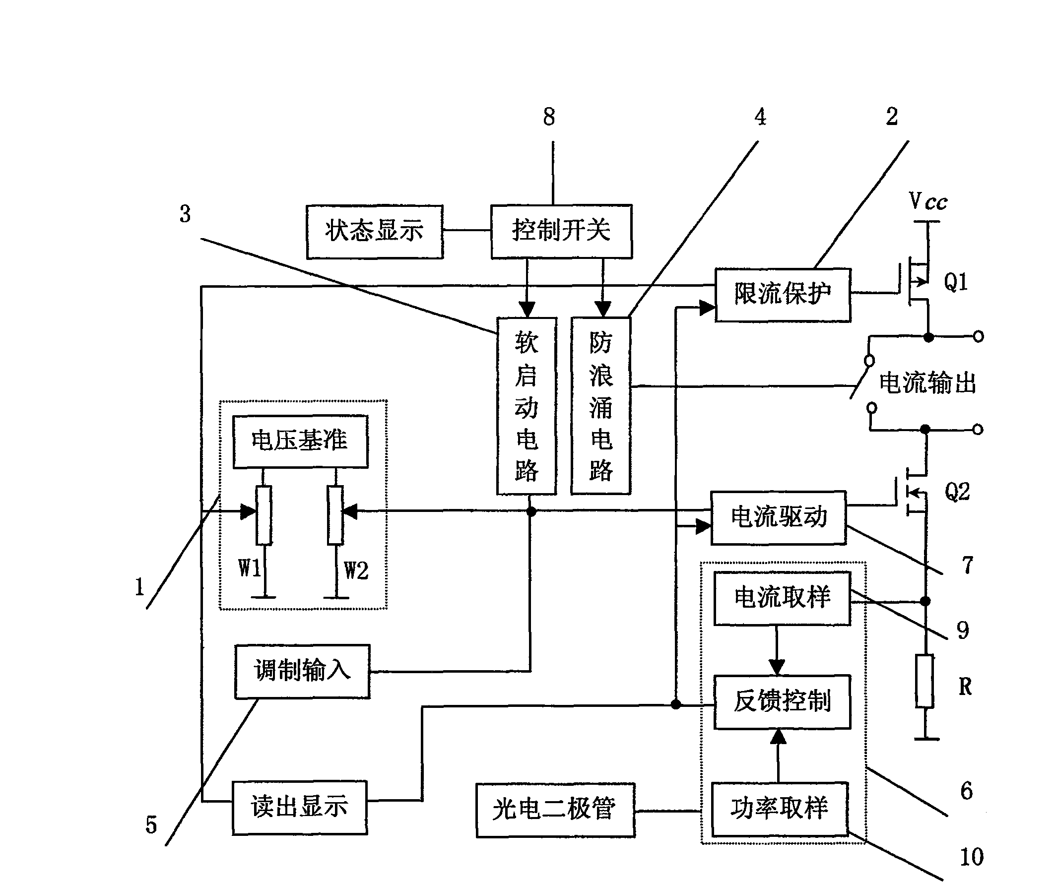
[0021] The principle block diagram of the driver voltage control current source is as follows: figure 1 shown. The voltage reference circuit 1 is composed of a voltage reference LM336-2.5 and a 9.1 kohm resistor, which provides an accurate and stable reference voltage for the circuit to control the output current and preset limit current. Potentiometer W1 is used to adjust the limit current, and potentiometer W2 is used to adjust the output current. The current limiting protection circuit 2 ensures that the output current does not increase when it reaches the limiting current, and maintains the set current unchanged. The current drive circuit 7 converts the control voltage into an output current. The high-power semiconductor device Q1 provides driving current for the laser diode, and the high-power semiconductor device Q2 can be a Darlington transistor or a field effect transistor. The present invention uses a power MOS transistor IRF530. When a large current drive is requi...

Embodiment 2

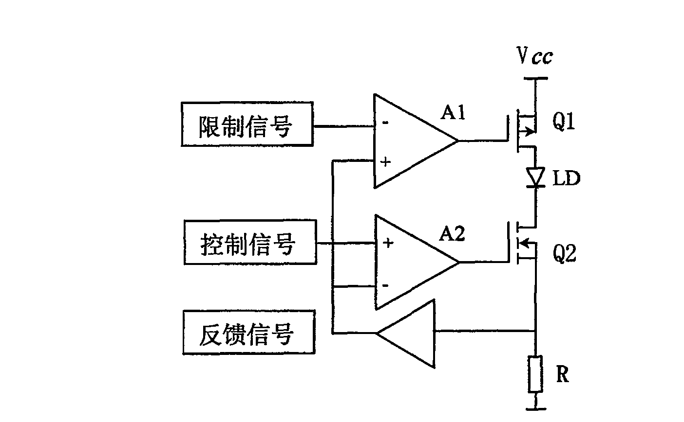
[0023] The block diagram of the current limiting protection circuit is as follows: figure 2 shown. The circuit includes a P-channel enhanced field effect transistor Q1 and an N-channel enhanced field effect transistor Q2; the gates of the field effect transistors Q1 and Q2 are connected to the operational amplifiers A1 and A2 respectively; the drain of Q1 is connected to the laser diode LD The anode of Q2 is connected to the cathode of the laser diode LD; the source of Q1 is connected to the working power supply V CC The source of Q2 is connected to the sampling resistor R; the limit signal output by the potentiometer W1 is connected to the inverting terminal of the operational amplifier A1, and the control signal output by the potentiometer W2 is connected to the non-inverting terminal of the operational amplifier A2, which comes from the sampling resistor R The feedback signal is connected to the non-inverting terminal of the operational amplifier A1 and the inverting term...

Embodiment 3

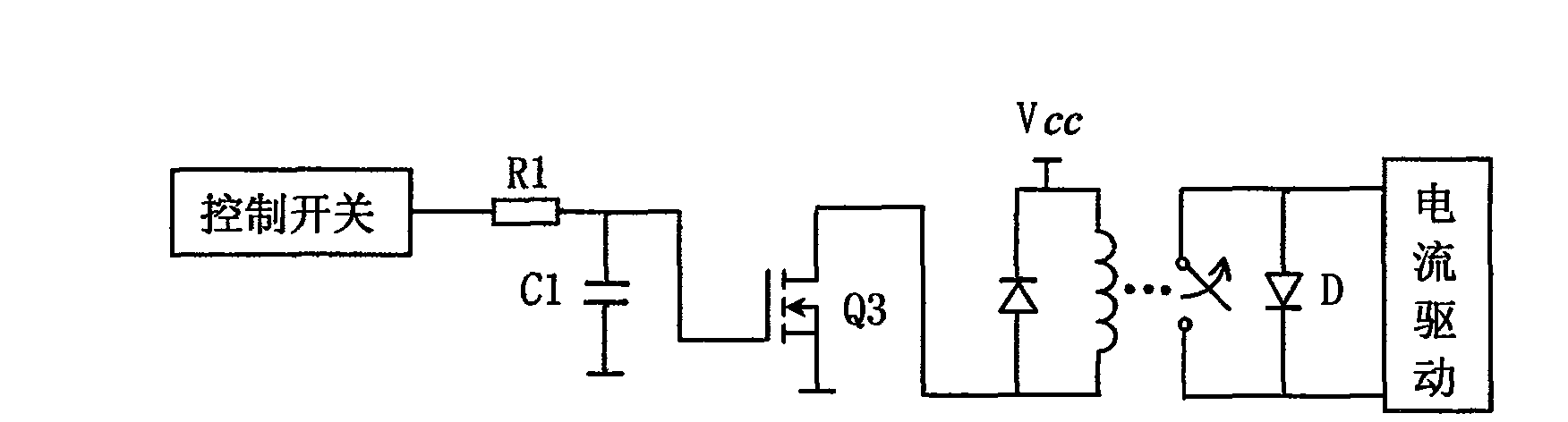
[0027] The block diagram of anti-surge circuit is as follows: image 3 shown. The circuit includes an RC charging circuit composed of R1 and C1, an N-channel enhanced field effect transistor Q3, and a normally closed solid-state relay. The gate of the field effect transistor Q3 is connected to the resistors R1 and C1, the other end of C1 is grounded, the drain of the field effect transistor Q3 is connected to the relay, and the source of the field effect transistor Q3 is grounded. The model of the field effect transistor Q3 may be 2sk1458.

[0028] The working principle of this circuit is: the anode and cathode of the laser diode LD are connected in parallel with the two normally closed terminals of the relay, so the cathode and anode of the LD are short-circuited and protected. When the driver is turned on, if the control switch is not turned on, the LD is still short-circuited. Only after the control switch 8 is turned on, the normally closed end of the relay will be opene...


PUM


Abstract

The high-power laser diode driver of the present invention is used for driving high-power laser diodes or laser diode arrays and providing complete protection equipment. The core part is the voltage controlled current source. The voltage control current source circuit board consists of a voltage reference circuit (1), a current limiting protection circuit (2), a soft start circuit (3), an anti-surge circuit (4), a modulation input circuit (5), and a feedback control circuit (6) Constituted with a current drive circuit (7). The invention adopts the principle of negative feedback to stabilize the output current, and can provide two drive modes of constant current drive and constant power drive. The constant current drive mode can precisely set the working current and limiting current of the laser diode, and the long-term current stability is 38ppm. In the constant power driving mode, the output current can be automatically adjusted to ensure that the laser diode LD works in a constant power state. Current-limit protection and soft-start protection provide fast, reliable and safe driving of the laser diode.

Description

technical field [0001] The invention relates to an instrument for driving high-power laser diodes or laser diode arrays, in particular to a driver providing complete protection for high-power laser diodes. Background technique [0002] All kinds of amplifiers in optical fiber communication systems use laser diodes as light sources, and the laser diodes are driven by dedicated drivers with special functions. [0003] A laser diode is a miniaturized laser that is excited by direct pumping with a semiconductor material as the working substance. However, a laser diode is a device with high power density and extremely high quantum efficiency. It has a poor ability to withstand electrical shocks. A small current will cause a large change in optical power output and device parameters (such as lasing wavelength, noise, etc.) Performance, mode jitter) changes, these changes directly endanger the safe use of the device, so complete protection measures are of great significance to the...

Claims


Application Information

Patent Timeline
Patent Type & Authority Patents(China)
IPC IPC(8): H01S5/042H01S5/062G05F1/10
Inventor 单江东田小建邓军汝玉星
Owner JILIN UNIV
Why Eureka
Try Eureka