Tuneable phase shfter and/or attenuator

A phase shifter and attenuator technology, applied in the field of optically adjustable phase shifters and/or attenuators, can solve the problems of high power loss, signal distortion and noise, and discontinuous step shifting

Inactive Publication Date: 2006-01-25
EUROPEAN SPACE AGENCY
View PDF2 Cites 9 Cited by
  • Summary
  • Abstract
  • Description
  • Claims
  • Application Information

AI Technical Summary

Problems solved by technology

However, ferroelectric phase shifters have considerable power loss, signal distortion, and noise, and can only provide discontinuous step phase shifting

Method used


Image

  • Tuneable phase shfter and/or attenuator
  • Tuneable phase shfter and/or attenuator
  • Tuneable phase shfter and/or attenuator

Examples


Embodiment Construction

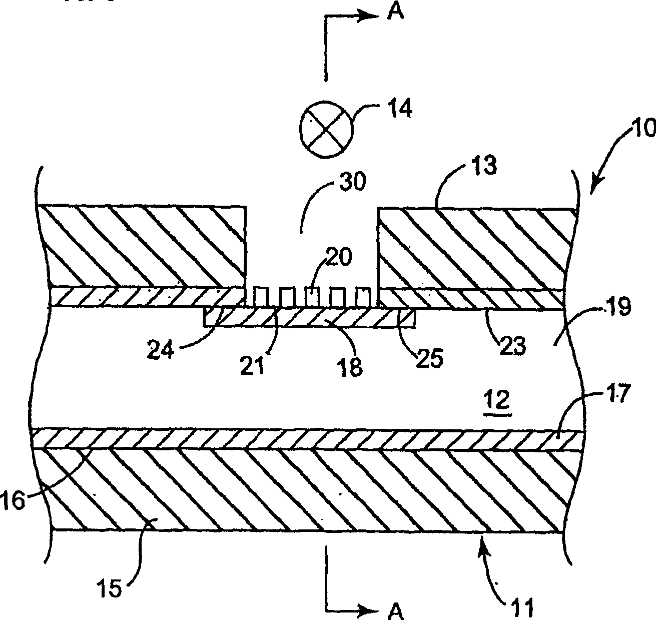
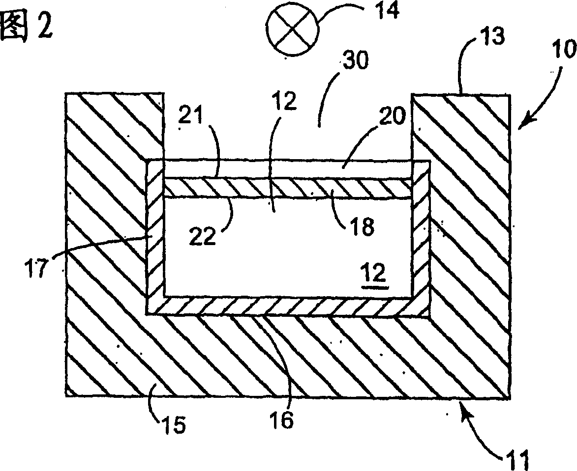
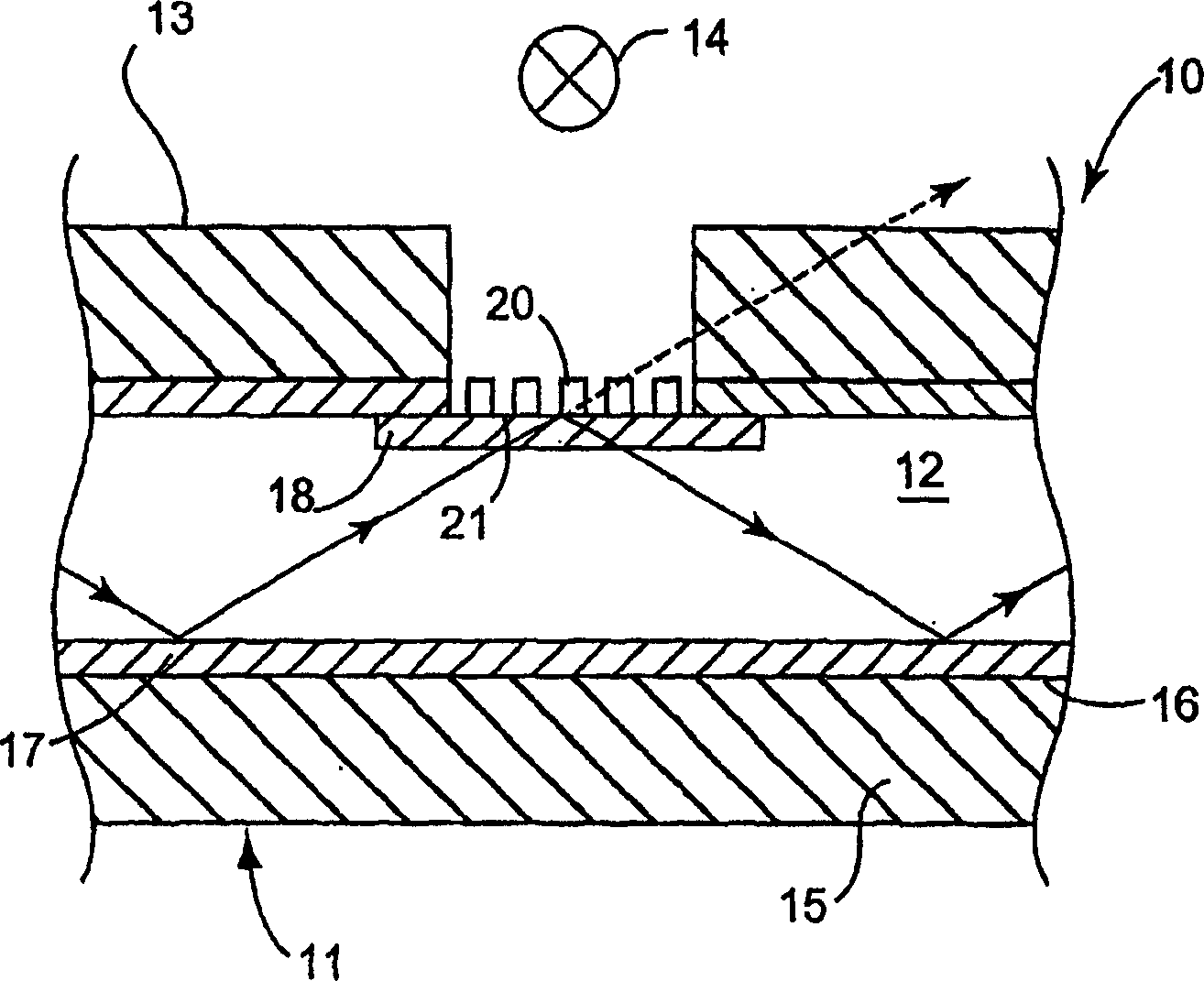
[0031] figure 1 The tunable phase shifter 10 shown in and 2 includes a waveguide 11 having a channel 12 extending along the length of the waveguide 11 and a hole formed in one side 13 of the waveguide 11. The adjustable phase shifter 10 may also include a metal grid 20 to avoid loss caused by the radiation of microwave, millimeter wave or submillimeter wave inside the waveguide to the outside of the waveguide system.

[0032] An optically sensitive layer 18 is arranged within the channel 12 of the waveguide 11 such that it extends substantially across the aperture. A tunable illumination source 14 emits that part of the spectrum of light (infrared, visible, ultraviolet, etc.) that is better absorbed by the photosensitive material in the waveguide. The light source 14 is arranged outside the waveguide such that radiation emitted by the light source 14 impinges on an area of ​​the photosensitive layer 18 exposed by the hole 30 formed in the side wall 13 of the waveguide 11 . T...


PUM


Abstract

The invention relates to a tuneable phase shifter and / or attenuator comprising a waveguide having a channel and a piece of photo-responsive material (18) disposed within the waveguide along an internal wall of said channel, a light source disposed outside the waveguide to emit light through an aperture (30) of said internal wall to impinge on at least part of an outside surface of said piece of photo-responsive material (18).

Description

technical field [0001] The present invention relates to a phase shifter and / or attenuator, in particular to an optically adjustable phase shifter and / or attenuator capable of operating in microwave, millimeter wave and submillimeter wave bands. Such phase shifters and / or attenuators may be used in a variety of applications including, but not limited to, phase shift keying circuits, terahertz imaging, transceivers, and phased array antennas. Background technique [0002] As far as the submillimeter band is concerned, terahertz technology is mainly used for surface, astronomical and earth exploration. However, many substances that are opaque in the visible and infrared regions are transparent to terahertz waves (0.1 THz to 10 THz). As a result, applications of terahertz technology have recently expanded to include applications such as aeronautical navigation (terahertz waves can pass through clouds and fog), medical imaging (the ability to examine human tissue without potenti...

Claims


Application Information

Patent Timeline
Patent Type & Authority Applications(China)
IPC IPC(8): H01P1/18H01P1/22
CPCH01P1/222H01P1/182H01P1/18H01P1/20
Inventor 达瑞奥·C.·卡斯蒂格利昂路伊萨·迪阿斯易尼古·艾迪拉-乌尔泽因-奎戴维·B.·哈斯科特德里克·简津斯亚历山大·V·S·B·雷森亚历克·J.·迈克卡尔丹詹姆斯·P.·奥尼尔乔治·泰尼恩特-瓦利纳斯弗兰克·万·德·瓦特尔阿尔弗雷德·A.·津彼得·德·玛格特克里斯·曼
Owner EUROPEAN SPACE AGENCY
Why Eureka
Try Eureka