

Equipment for automatic opening and closing uptake of indoor machine of air conditioner
A technology for automatic opening and closing of indoor units of air conditioners, which is applied in air conditioning systems, space heating and ventilation, household heating, etc., and can solve the problem of incomplete closure and overall beauty of the appearance, as well as unsatisfactory manufacturability and reliability. Perfect, complex structure and other issues, to achieve the effect of preventing dust and foreign matter from entering the air conditioner, good stability and reliability, and simple overall structure
- Summary
- Abstract
- Description
- Claims
- Application Information
AI Technical Summary
Problems solved by technology
Method used
Image

Examples
Embodiment Construction
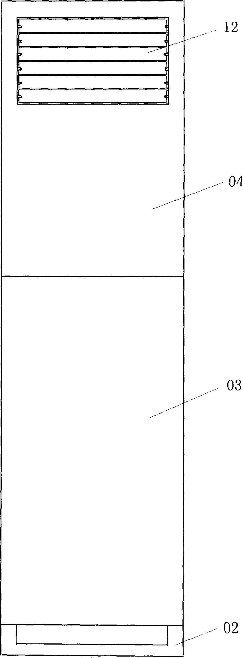
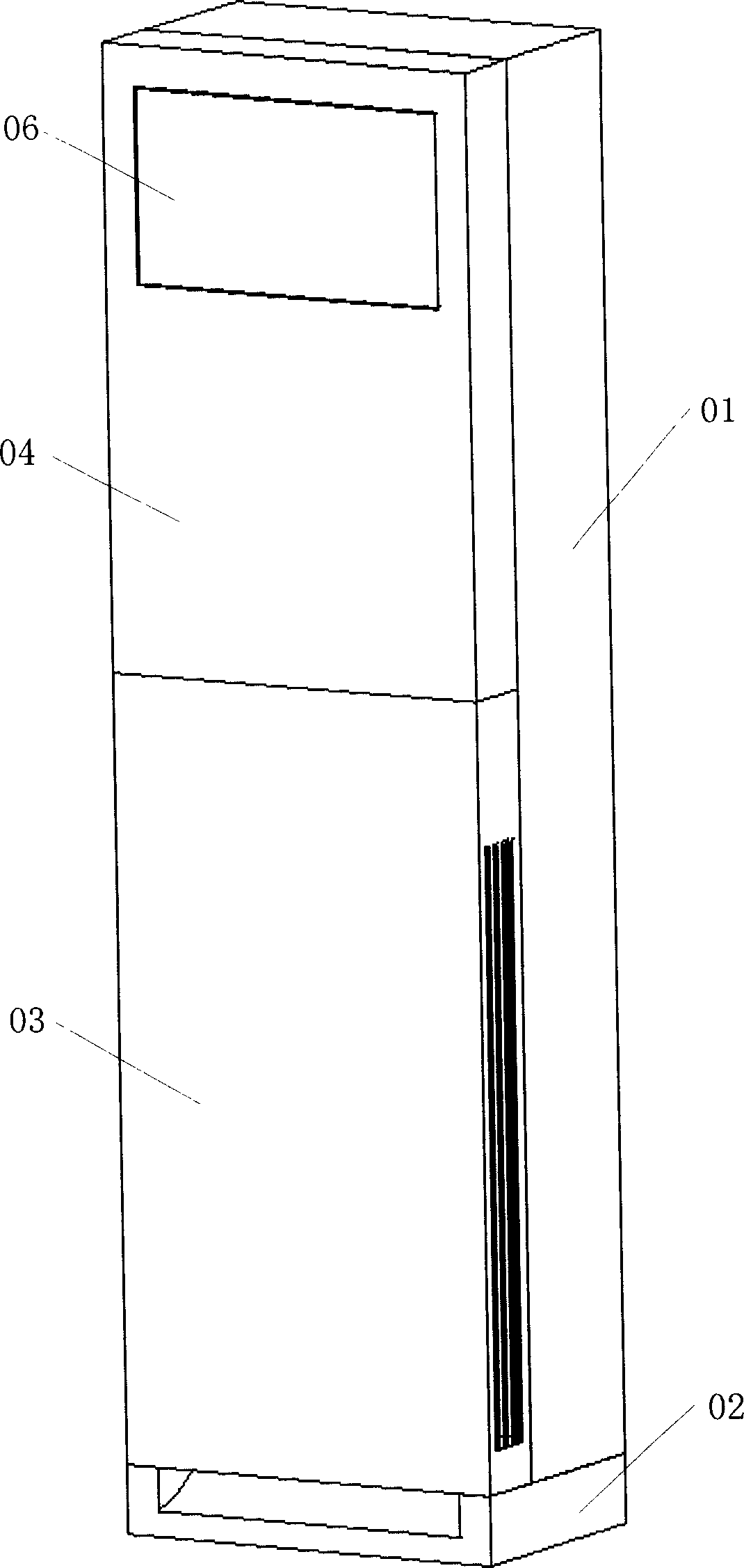
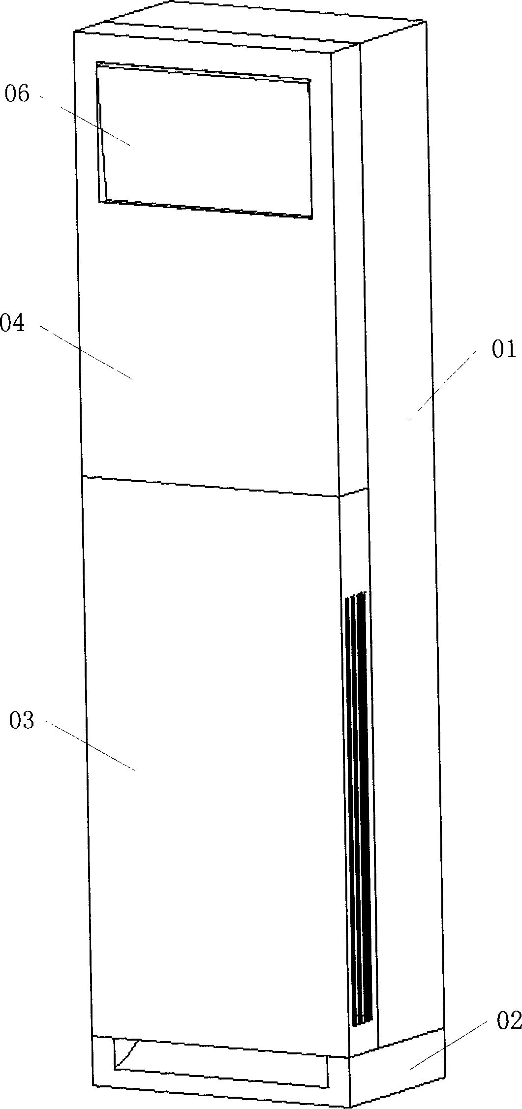
[0027] The detailed description follows with reference to the drawings, wherein like reference numerals refer to like parts throughout the different views. Explanation of reference signs: box body 01, base 02, lower panel 03, upper panel 04, air outlet device mounting base 05, air outlet door 06, connecting rod 07, worm wheel 08, worm screw 09, drive motor 10, guide wheel 11, horizontal Wind deflector 12, vertical wind deflector 13, fixed guide pin 101, upper guide groove 102a, lower guide groove 102b.
[0028] The split floor type air conditioner indoor unit of the present invention comprises a casing consisting of a box body 01, an upper panel 04, a lower panel 03, and a base 02, such as figure 2 As shown, the upper panel 04 is used to cover the upper part of the front opening of the box body 01, and the upper part of the upper panel 04 has an air outlet; the lower panel 03 is used to cover the lower part of the front opening of the box body 01, and the lower panel 03 has s...
PUM
 Abstract
Description
Claims
Application Information