Illuminating device and projection type video display

A technology for lighting devices and display devices, which is applied to projection devices, optics, instruments, etc., can solve the problem of inability to use light-emitting diodes, etc., and achieve the effect of improving parallelism

Inactive Publication Date: 2006-02-01
SANYO ELECTRIC CO LTD
View PDF3 Cites 13 Cited by
  • Summary
  • Abstract
  • Description
  • Claims
  • Application Information

AI Technical Summary

Problems solved by technology

[0003] However, it is practically impossible to use ...

Method used


Image

  • Illuminating device and projection type video display
  • Illuminating device and projection type video display
  • Illuminating device and projection type video display

Examples


Embodiment approach 1

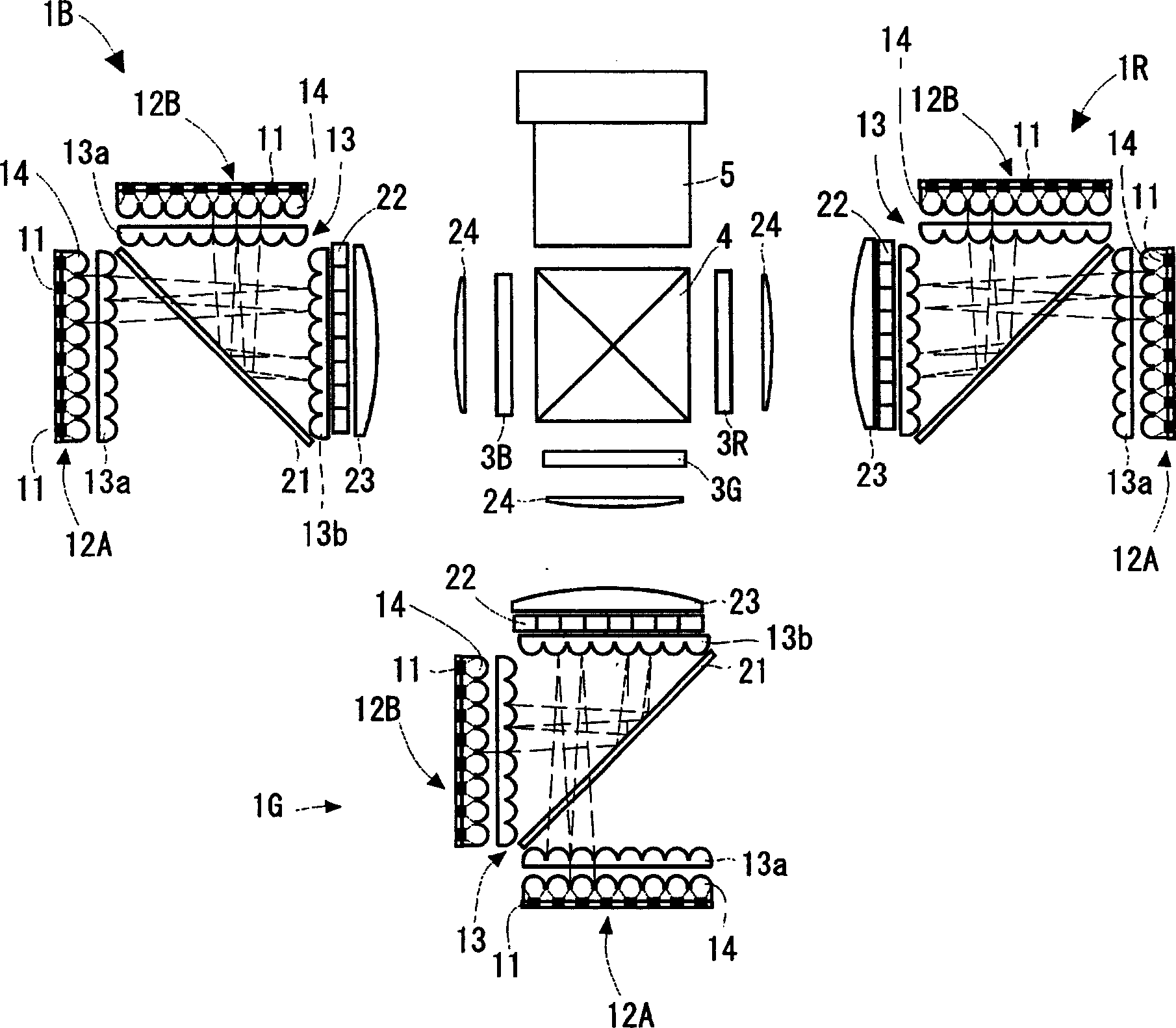
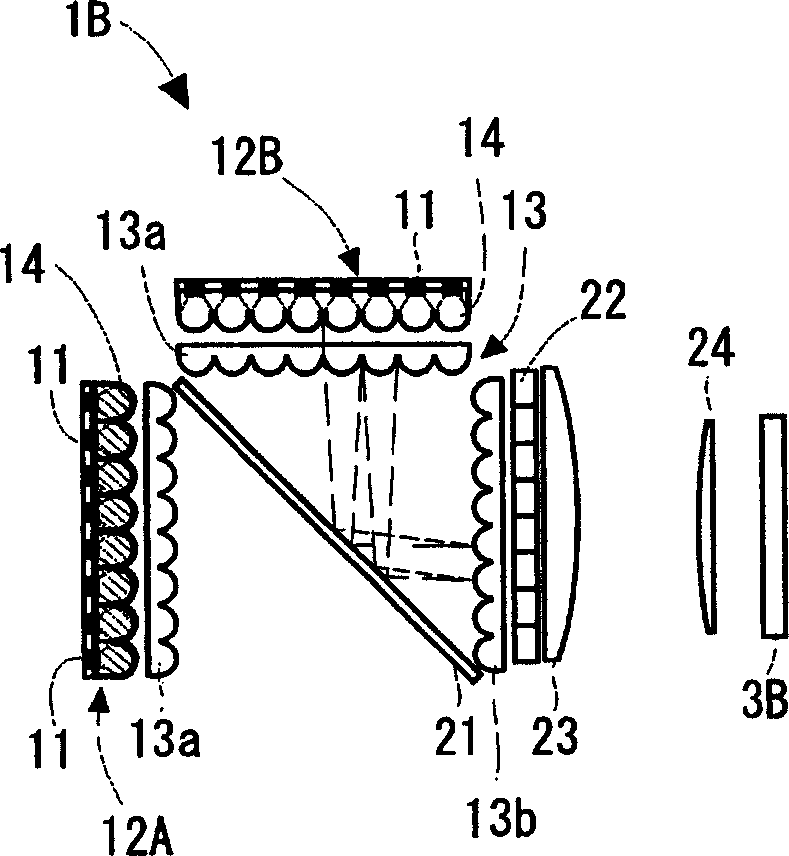
[0061] Below, according to Figure 1 to Figure 11 A projection display device according to a first embodiment of the present invention will be described. In addition, in any of the examples of the first embodiment, the lights of the plurality of light sources are all introduced into the same optical path. However, a different structure using the wavelength of light (such as a structure using a dichroic mirror, etc.) or a different structure using polarized light (such as using the transmission of P-polarized light and the reflection of S-polarized light and combining them will not be used. Structure). In other words, a configuration is realized in which light of the same color or polarization can be used as a light source.

[0062] figure 1 It is an optical system representing a three-panel projection display device. This projection display device includes three lighting devices 1R, 1G, and 1B (hereinafter, when each lighting device is not specifically shown, it is indicat...

Embodiment approach 2

[0091] Below, according to Figure 12 to Figure 22 A lighting device and a projection display device according to a second embodiment of the present invention will be described.

[0092] Figure 12 It is an explanatory drawing which shows 100 A of illumination devices. A first light source 102 (hereinafter, also referred to as symbol 102A) and a first polarization conversion device 103 (hereinafter, also referred to as symbol 103A) are disposed on the first light incident surface of the polarization combining element (optical path changing mechanism) 101. case), and a second light source 102 (hereinafter also referred to as 102B) and a second polarization conversion device 103 (hereinafter also referred to as 103B) are disposed on the second light incident surface. The first light incident surface and the second light incident surface intersect at 90 degrees. In addition, the polarized light synthesizing film (polarized light separating film) of the above-mentioned polarize...


PUM


Abstract

An illuminating device comprises a first light source in which LED chips are arranged in an array shape and a second light source in which LED chips are arranged in an array shape. The two light sources of each illuminating device are arranged such that the main light-emission optical axes of the light sources are perpendicular to each other. Moreover, a time-division switching mirror is provided at a crossing position between the main light-emission optical axes. The first light source and the second light source alternately emit pulses of light. The pulsed emission is a method of supplying a large amount of electric currents to the LED chips in a short time period, and a light-emitting amount increases compared to a steady-state emission of the LED chips. The time-division switching mirror becomes a transmitting state when the first light source is lighted, and becomes a reflecting state when the second light source is lighted.

Description

technical field [0001] The present invention relates to an illuminating device and a projection display device. Background technique [0002] Illumination devices used in liquid crystal projectors and the like generally consist of lamps such as ultra-high pressure mercury lamps, metal halide lamps, and xenon lamps, and parabolic reflectors that collimate the irradiated light. In addition, in this illuminating device, in order to reduce the unevenness of the light quantity on the irradiated surface, it has a function of integrating (integrate) using a pair of fly eye lenses (using optical devices to sample a plurality of predetermined shapes formed in a plane). Lighting Area Overlap function that spotlights on lighting objects). Furthermore, in recent years, attempts have been made to use light-emitting diodes (LEDs) as light sources from the viewpoint of weight reduction, miniaturization, etc. (see Japanese Patent Application Laid-Open No. 10-186507). [0003] However, it ...

Claims


Application Information

Patent Timeline
IPC IPC(8): G03B21/14G03B21/20G03B21/28G03B21/00
Inventor 池田贵司吉居正一横手惠纮
Owner SANYO ELECTRIC CO LTD
Why Eureka
Try Eureka