

Macro/micro driven two-degree-of-freedom high-acceleration high-precision parallel positioning system
A high-acceleration, positioning system technology, applied in measurement devices, instruments, optical devices, etc., can solve the problems of large linear motion inertia, poor end effector stiffness, low positioning accuracy, etc., and achieve good kinematic performance and dynamics. The effect of high performance, large load capacity and high positioning accuracy
- Summary
- Abstract
- Description
- Claims
- Application Information
AI Technical Summary
Problems solved by technology
Method used
Image

Examples
specific Embodiment approach 1
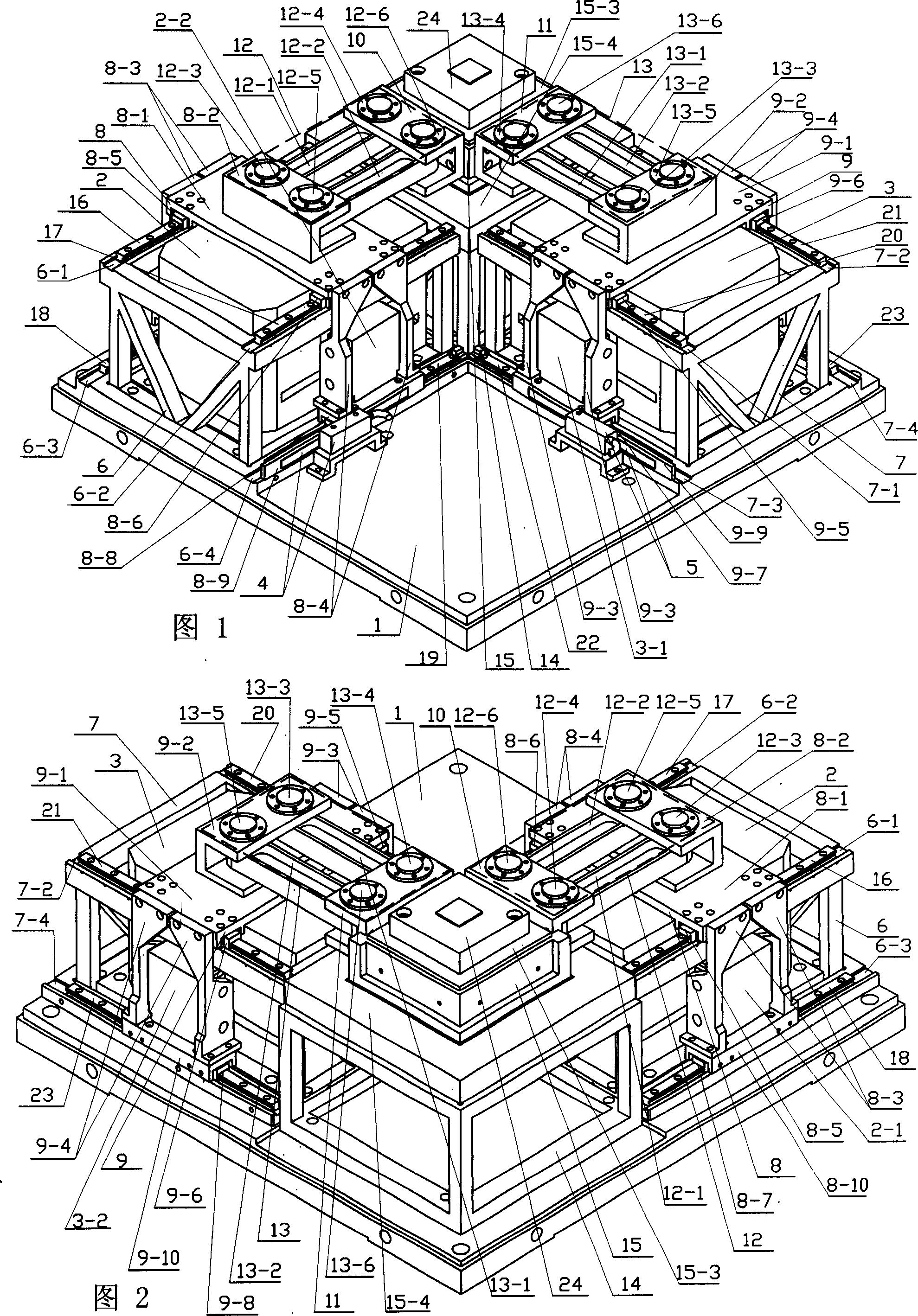
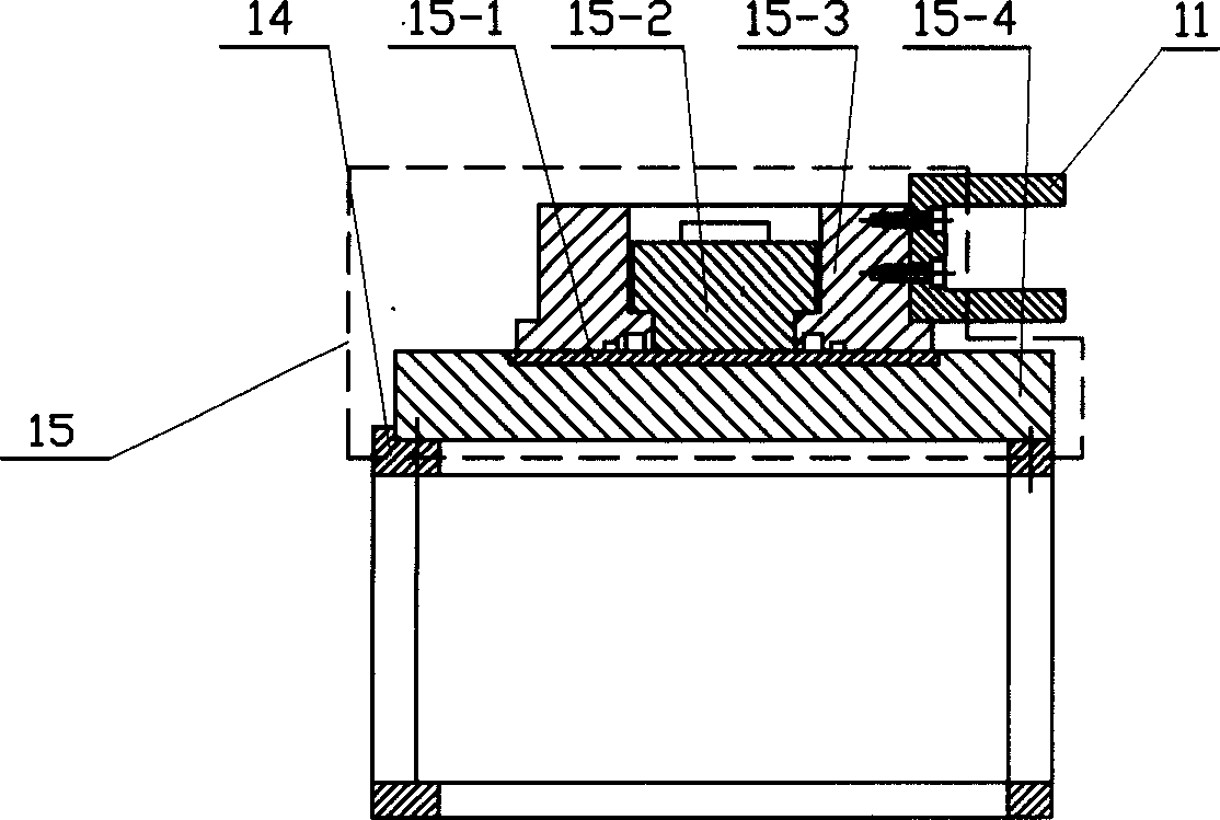
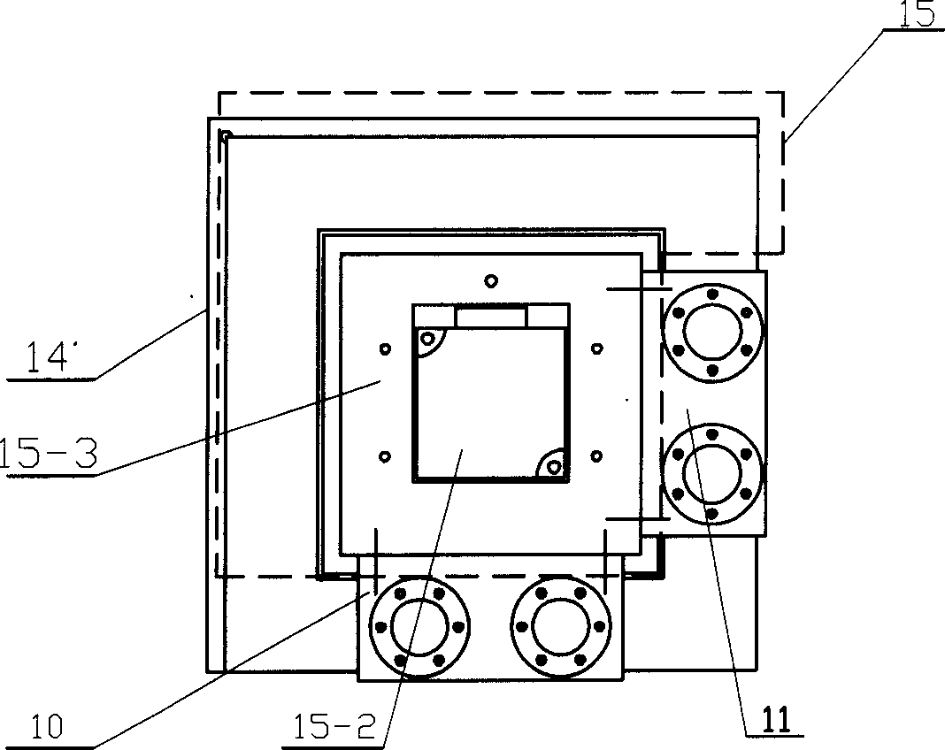
[0006] Specific Embodiment 1: This embodiment is described in conjunction with Fig. 1 and Fig. 2. This embodiment consists of a base 1, an X-axis linear drive device 2, a Y-axis linear drive device 3, an X-axis linear guide rail, a Y-axis linear guide rail, an X-axis Linear grating 4, Y-axis linear grating 5, X-axis guide rail support 6, Y-axis guide rail support 7, X-axis moving platform assembly 8, Y-axis moving platform assembly 9, X-axis end platform 10, Y-axis end platform 11. The X-axis parallel linkage mechanism 12, the Y-axis parallel linkage mechanism 13, the air bearing 14, and the end output platform 15 are composed; the X-axis guide rail support 6 and the Y-axis are respectively fixed on the opposite corners of the base 1 The guide rail support 7, the base 1 at the intersection of the axis of the X-axis guide rail support 6 and the axis of the Y-axis guide rail support 7 is fixed with an air-floating support 14, the upper end surface of the air-floating support 14 a...
specific Embodiment approach 2
[0007] Specific embodiment two: This embodiment is described in conjunction with Fig. 1 and Fig. 2. The X-axis linear guide rail of this embodiment consists of an X-axis upper left linear guide rail 16, an X-axis upper right linear guide rail 17, an X-axis lower left linear guide rail 18, and an X-axis linear guide rail. The right linear guide rail 19 on the lower layer of the axis; the left linear guide rail 16 on the upper layer of the X axis is fixed in the groove 6-1 at the upper left end of the X axis guide rail support 6, and the right linear guide rail 17 on the upper layer of the X axis is fixed on the X axis guide rail support 6 In the groove 6-2 at the upper right end of the X-axis, the left linear guide rail 18 of the lower layer of the X-axis is fixed in the groove 6-3 of the lower left end of the X-axis guide rail support 6, and the right linear guide rail 19 of the lower layer of the X-axis is fixed in the X-axis guide rail support In the lower right end groove 6-...
specific Embodiment approach 3
[0009] Specific embodiment three: This embodiment is described in conjunction with Fig. 1 and Fig. 2. The Y-axis linear guide of this embodiment consists of the Y-axis upper left linear guide 20, the Y-axis upper right linear guide 21, the Y-axis lower left linear guide 22, and the Y-axis linear guide 22. The right linear guide rail 23 of the lower layer of the axis is composed; the left linear guide rail 20 of the upper layer of the Y axis is fixed in the upper left end groove 7-1 of the Y axis guide rail support 7, and the right linear guide rail 21 of the upper layer of the Y axis is fixed on the Y axis guide rail support 7 In the upper right groove 7-2 of the Y axis, the left linear guide rail 22 of the lower layer of the Y axis is fixed in the groove 7-3 of the lower left end of the Y axis guide rail support 7, and the right linear guide rail 23 of the lower layer of the Y axis is fixed in the Y axis guide rail support In the lower right end groove 7-4 of seat 7. Adopting...
PUM
 Abstract
Description
Claims
Application Information