A parallel handle system and method for designing the like

A handle, human hand technology, applied in the field of parallel handles and parallel handle systems, which can solve problems such as discomfort

Inactive Publication Date: 2006-02-08
斯蒂芬L・提林姆
View PDF6 Cites 2 Cited by
  • Summary
  • Abstract
  • Description
  • Claims
  • Application Information

AI Technical Summary

Problems solved by technology

However, tools based on triangular lever systems are often uncomfortable to use

Method used


Image

  • A parallel handle system  and method for designing the like
  • A parallel handle system  and method for designing the like
  • A parallel handle system  and method for designing the like

Examples


Embodiment Construction

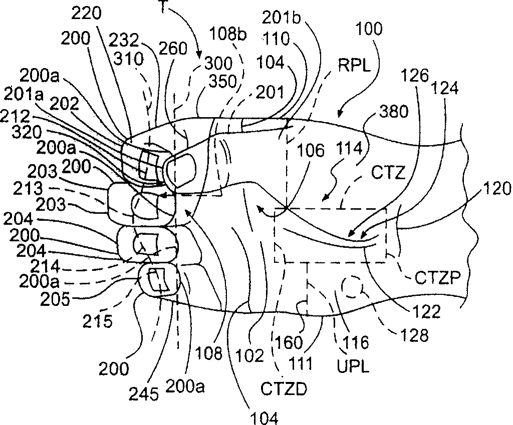
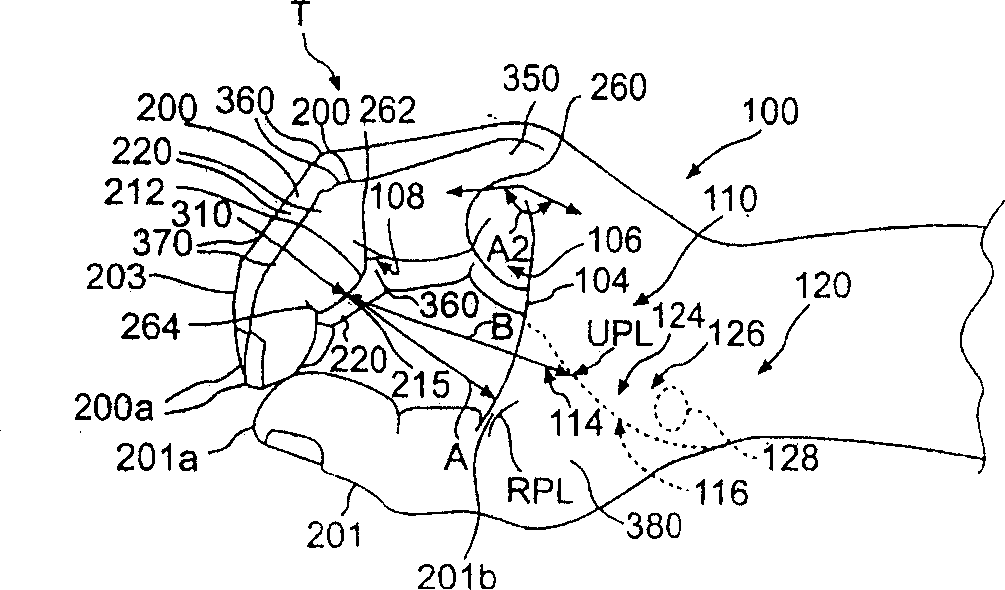
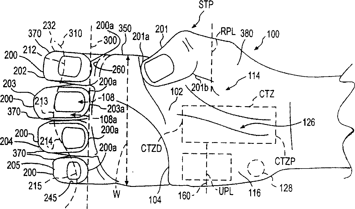
[0035] In order to describe the subject matter of the present invention more clearly and concisely, the definitions of the T-position, the extended T-position STP and the closed T-position CTP are as follows to provide guidance for the meaning of specific terms. Used in the following written descriptions. Also, it should be understood that the phraseology or terminology used herein is for the purpose of description only and not limitation. The following discussion relates to the area of ​​the hand relevant to the present invention, see Figure 1 to Figure 6 .

[0036] figure 1 is a view of the palm 102 belonging to the hand 100, figure 2 is a view of the radial side 110 of the hand 100 . figure 1 and figure 2 Hand 100 is depicted in a T-position.

[0037] The T-position is the posture of the hand 100 when the fingertips 200a of the long fingers 200 are substantially aligned and the fingertips 201a of the thumb 201 are opposed to the gap 320 between the index finger 202...


PUM


Abstract

A parallel handle system and method for designing the handle system for use with tools or control mechanisms, that includes a handle having a radial section (440) having a side for receiving the thumb and a side for receiving the index finger, the radial section liaving a surface for engaging a portion of the palma surface of the hand, a middle section (430) having a side for receiving at least a portion of the middle finger and at least a portion of the ring finger and a surface that avoids placing undue pressure on a surface of the hand located over the carpal tunnel, and an ulnar section (420) having a side for receiving the small finger and a surface for engaging a portion of the palmar surface of the hand so as to position the end of the small finger.

Description

technical field [0001] The present invention relates to parallel handles, parallel handle systems and methods for designing parallel handle systems that can be operated with one hand to hold or use tools such as those that can hold, clamp, cut and pierce objects. The invention also relates to parallel handles and parallel handle systems having control mechanisms for operating various devices and performing different functions. [0002] priority claim [0003] This application claims the benefit of and is a continuation-in-part of US Application Serial No. 10 / 279,111, filed October 24, 2002, the entire disclosure of which is hereby incorporated by reference. This application also claims the benefit of and is a continuation-in-part of International Application No. PCT / US02 / 33956 filed on October 24, 2002, which has been published in English under PCT Section 21(2), its complete The disclosure is hereby incorporated by reference. This application further claims the benefit of ...

Claims


Application Information

Patent Timeline
Patent Type & Authority Applications(China)
IPC IPC(8): A45C13/26B25G3/00A61B17/00A61B17/28A61B17/30A61B17/32A61B17/88
CPCA61B2017/00424A61B2017/0046A61B17/8875A61B2017/2931A61B2017/2919A61B2017/2927A61B2017/32113A61B17/3201A61B2017/00477A61B17/30A61B17/3213B25G1/102A61B2017/2939A61B2017/2918A61B17/2909A61B2017/2929
Inventor 斯蒂芬L・提林姆
Owner 斯蒂芬L・提林姆
Why Eureka
Try Eureka