Fan coil metering control apparatus and heat metering method

A technology for fan coil units and control devices, applied in measuring devices, measuring heat, computer control, etc., can solve problems such as unfairness, uncertainty of household division, and failure to realize

Inactive Publication Date: 2006-02-15
LIAONING HUANJIA HIGH TECH ENERGY SAVING TECH ENG
View PDF0 Cites 9 Cited by
  • Summary
  • Abstract
  • Description
  • Claims
  • Application Information

AI Technical Summary

Problems solved by technology

[0003] Using traditional heat meters to solve the problem of household metering of central air-conditioning not only has th

Method used


Image

  • Fan coil metering control apparatus and heat metering method
  • Fan coil metering control apparatus and heat metering method
  • Fan coil metering control apparatus and heat metering method

Examples


Embodiment Construction

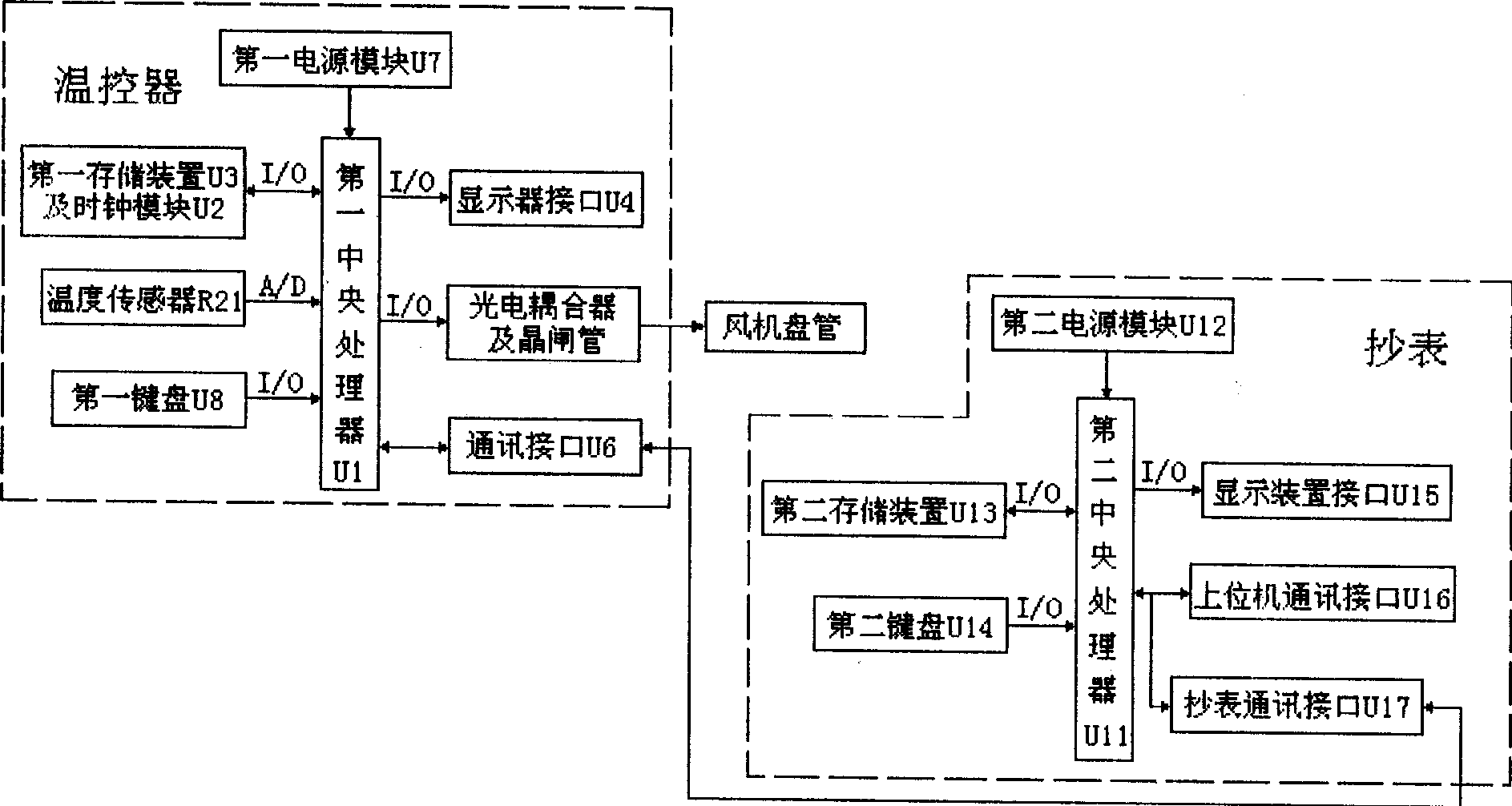
[0043] Such as figure 1 As shown, the fan coil metering control device of the present invention includes a thermostat and a meter reading adapted to the thermostat. The thermostat is installed in an air-conditioned room with a fan coil unit. The input end of the thermostat is connected to the The temperature sensor R21 of the air-conditioned room is connected (generally, the temperature sensor R21 is set in the thermostat), and the output terminal is connected to the control terminal of the high, medium and low gears of the fan coil unit, and communicates with the copy through the communication interface U6 Table for communication connection;

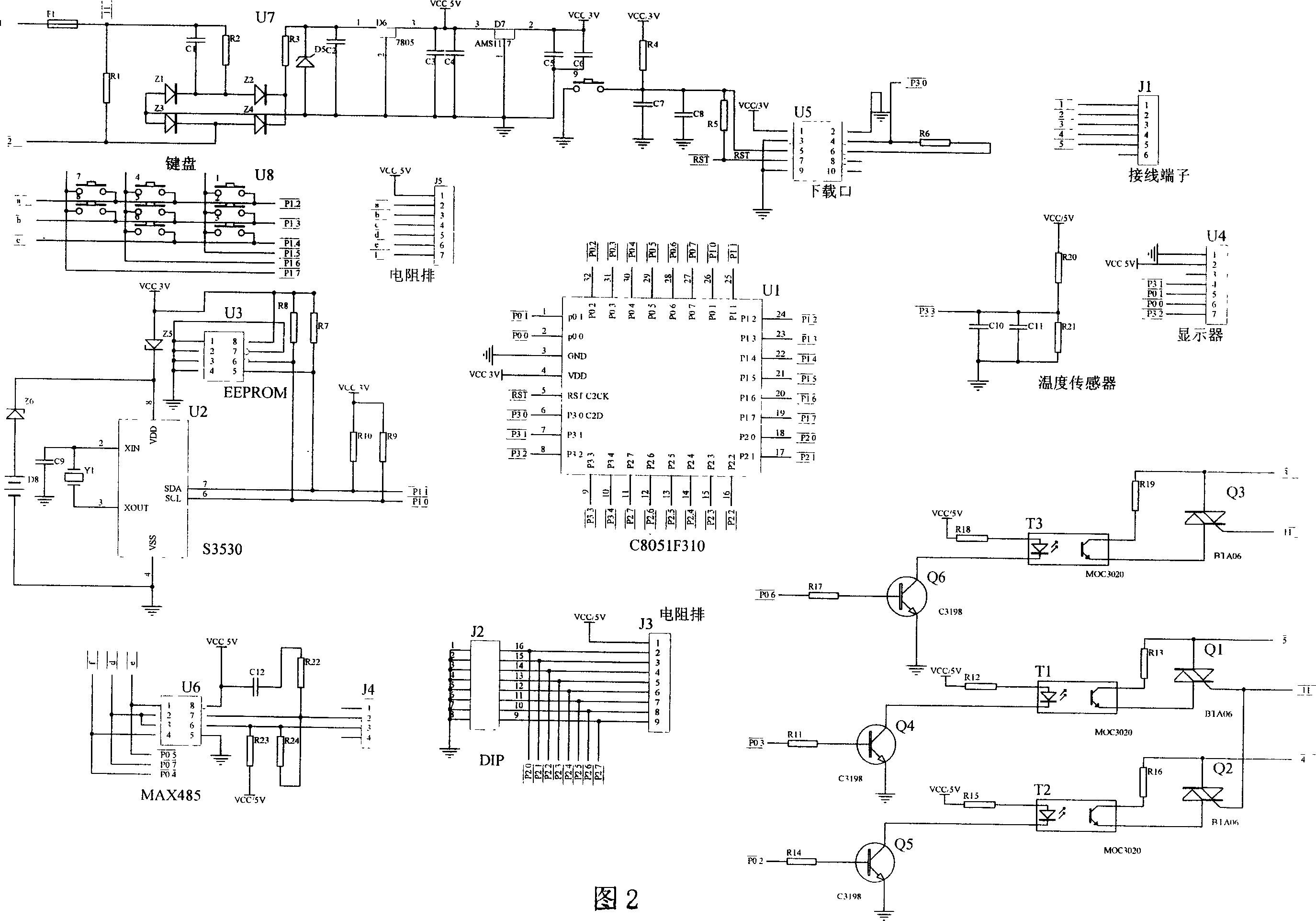
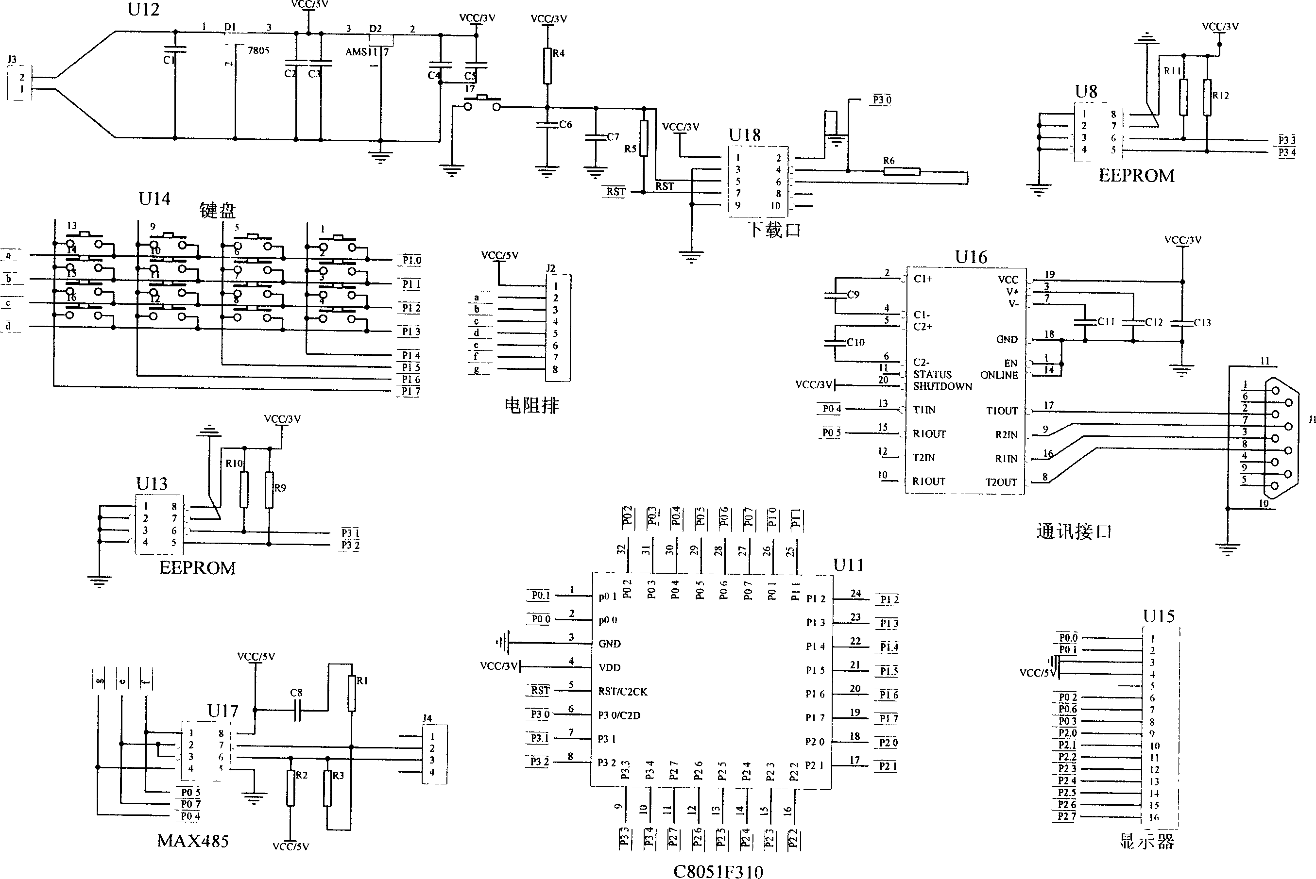
[0044] As shown in Figures 2 and 3, the temperature controller has a first central processing unit U1, its analog input terminal P3.3 is connected to the signal output terminal of the temperature sensor R21, and the output pin P3.3 of the first central processing unit U1. 1. P0.1, P0.0, and P3.2 are connected to the control pins of the...


PUM


Abstract

The invention provides a fan coil gauge control device and heat gauge method, which consists of temperature controller and meter reader. The temperature controller is fixed in the fan coil air-conditioning room, whose input end connects the temperature sensor and the output end connects fan coil high-medium-low controller by communication interface and meter reader, which comprises the following steps: 1) checking high-medium-low working heat value or cold value which sets in the temperature controller by contrasting product introduction; 2) gauging working program of temperature controller by present marking; 3) reading each fan coil heat equivalent which provides date individually after the heating or refrigerating season.

Description

technical field [0001] The invention relates to a heat energy metering control device and a metering method of a central air conditioner, in particular to a fan coil metering control device and a heat metering method. Background technique [0002] At present, the commonly used heat metering methods in the world are all completed by measuring the temperature difference and flow rate of the water flowing into the heat consumption unit, and calculating it according to the heat calculation formula. It has theoretical correctness and accuracy, but it often has inaccuracy and injustice in practical application. First of all, the accuracy of flow measurement is easily affected by water quality, and as the service life increases, the water quality will become more and more serious, so it is difficult to ensure the stability and accuracy of flow measurement; secondly, the room in the building There are large differences in heat load in different locations and orientations. In diffe...

Claims


Application Information

Patent Timeline
IPC IPC(8): G05B19/05G05B13/02G05B15/02G05D23/19G01K17/00G01D4/00
CPCY02B90/24Y04S20/30Y04S20/244Y02B70/3275Y02B70/30
Inventor 张帆张诚实周丽杰徐广艳
Owner LIAONING HUANJIA HIGH TECH ENERGY SAVING TECH ENG
Why Eureka
Try Eureka