Method and apparatus for adjusting scan area in tomography equipment

A technology of tomography and scanning area, which is applied in the field of adjusting the scanning area to achieve the effect of time-saving operation

Inactive Publication Date: 2006-02-22
SIEMENS AG
View PDF0 Cites 14 Cited by
  • Summary
  • Abstract
  • Description
  • Claims
  • Application Information

AI Technical Summary

Problems solved by technology

[0004] In this case, the disadvantage is mainly that the patient must be exposed to a certain

Method used


Image

  • Method and apparatus for adjusting scan area in tomography equipment
  • Method and apparatus for adjusting scan area in tomography equipment
  • Method and apparatus for adjusting scan area in tomography equipment

Examples


Embodiment Construction

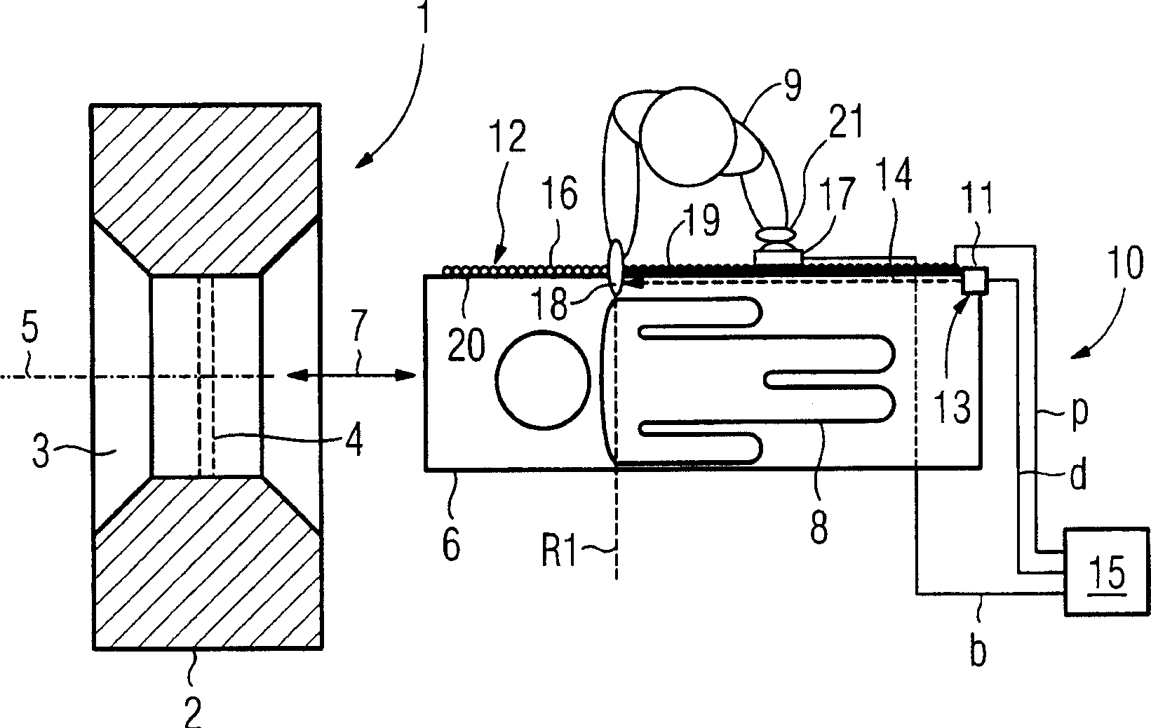
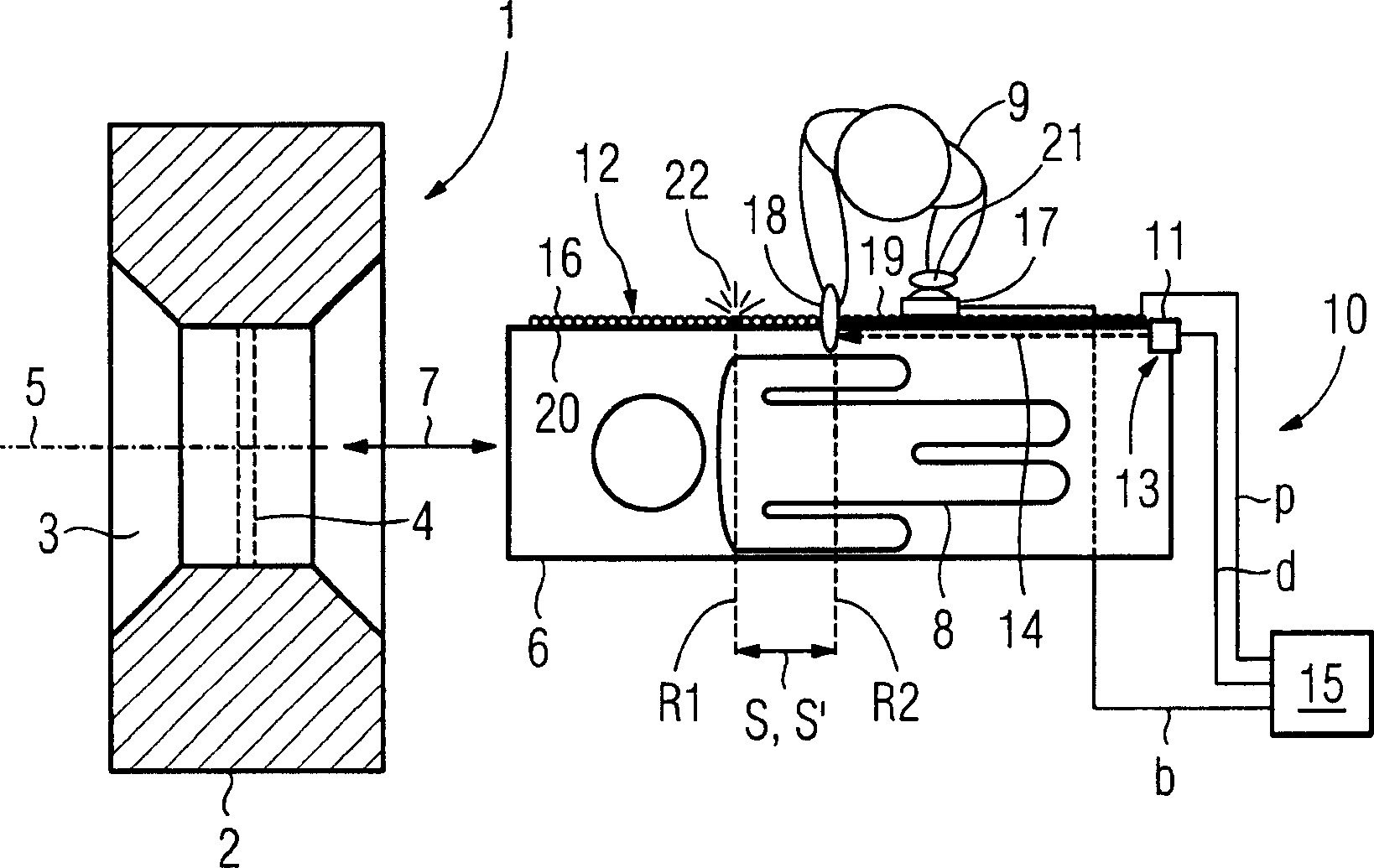
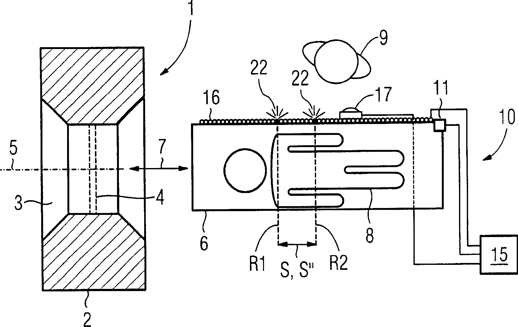
[0028] figure 1 A computed tomography system, hereinafter referred to as tomography system 1 for short, is shown schematically in a horizontal view. The tomographic apparatus 1 comprises a so-called gantry 2, i.e. a substantially annular support frame, around which a central through hole 3 is rotatably placed in a conventional manner an X-ray emitter not shown in the figure. - A detection unit, so that x-ray images can be obtained from different projection directions of a disc-shaped space, referred to below as the recording plane 4 . Here, the photographing plane 4 is approximately located in the middle of the through hole and is perpendicular to the axis 5 of the through hole.

[0029] The tomography system 1 also includes a table-shaped or bed-shaped patient couch 6 , which can be inserted in the insertion direction 7 into the through-opening 3 for the actual examination. figure 1 and 2 The patient couch is shown in a position completely drawn out of the opening 3 , on w...


PUM


Abstract

A method and an apparatus are provided for conveniently, quickly and intuitively adjusting a scanning region of a tomography device (1). At least one edge point (R1, R2) of a set-point scanning region (S') on a patient examination table (6) associated with the tomography device (1) is indicated by hand signals of a user. Via a distance sensor (11), mounted at a reference point (13) of the patient examination table (6), a distance from the edge point to the reference point is measured. From the measured distance, the position of the edge point (R1, R2) relative to the patient examination table (6) is determined, and a corresponding edge of a actual scanning region (S'') of the tomography device (1) is conformed to the derived position.

Description

technical field [0001] The invention relates to a method for adjusting a scan field in a tomography system. The invention also relates to a device for carrying out the method. In this context, the term tomography device generally refers to a medical technology device, in particular a computed tomography device or a magnetic resonance tomography device, which operates according to the layered imaging method. Background technique [0002] In particular, the so-called scan field must first be determined before the computerized tomography is performed on the patient. The scanning area refers to the body area of ​​the patient to be examined that is scanned during the examination of successive recordings of adjacent body layers and the area of ​​the patient's couch that corresponds to this body area. [0003] Up to now, this scanning area has usually been determined by means of a topogrammbild with internally stored information taken in the preparatory phase of the actual examin...

Claims


Application Information

Patent Timeline
IPC IPC(8): A61B6/03
CPCA61B6/547A61B6/469A61B6/08A61B6/032A61B6/04
Inventor 克斯廷·巴科罗伯特·卡格迈耶约翰尼斯·帕斯乔尔德
Owner SIEMENS AG
Why Eureka
Try Eureka